Two-seat biplane with tandem open cockpits.
Biplane
Eagle [1] DW-1 Eagle

Deliveries of Eagle Aircraft’s new ag-¬plane, manufactured by Bellanca, were planned to begin in October 1979. Designed from advanced glider technology, which en¬hances fuel efficiency, the Eagle was cer-tificated with 220 and 240 hp Continen¬tals and 275 and 350 hp Jacobs (all radi¬als); certification was pending with the 300¬hp Lycoming opposed powerplant.
Wood wings and steel tube fuselage, all Dacron-covered; spoilers on top surface of lower wings for more precise control at spray speed (65mph).
An agreement with Bellanca Aircraft Corporation of June 1979 was for Bellanca to manufacture Eagle on its behalf. Eagle production lasted until the early 1980s.
Eagle 300
First built: 1980.
Engine: 1 x Lycoming IO-540, 300 hp.
TBO: 1500 hrs.
Prop: Hartzell 3 blade, constant speed 86 in.
Seats: 1.
Length: 26 ft.
Height: 10.9 ft.
Wingspan: 55 ft.
Wing area: 386 sq.ft.
Wing aspect ratio: 15.1.
Max ramp wt: 5400 lbs.
Max take off wt: 5400 lbs.
Standard empty wt: 2650 lbs.
Max useful load: 2750 lbs.
Max landing wt: 4000 lbs.
Wing loading: 13.5 lbs/sq.ft.
Power loading: 18 lbs/hp.
Max useable fuel: 426 lbs.
Hopper capacity: 250 USG.
Climb rate: 750 fpm.
Climb @ 8000 ft: 450 fpm.
Service ceiling; 20,000 ft.
Max speed: 100 kts.
Working speed: 100 kts.
Fuel flow @ working speed: 103 pph.
Endurance @ working speed: 3.9 hr.
Stalling speed clean: 48 kts.
Turbulent air penetration speed: 103 kts.
Fixed tail-wheel undercarriage.
Fitted with spoilers.
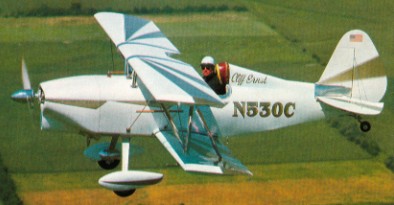
EAA Pee Wee
Single seat single engined biplane with con¬ventional three axis control. Conventional tail. Control inputs through stick for pitch/roll and pedals for yaw. Wings braced by struts. Undercarriage has three wheels in tail drag¬ger formation. Aluminium tube framework, with optional pod. Engine mounted between wings driving tractor prop¬eller.
Named Pee Wee after an early lightweight aircraft developed by Joe Kirk, one of EAA’s directors in the ’50s and ’60s, the Pee Wee machine is a tractor biplane powered by a KFM opposed twin engine with electric start. The design allows a pod to be incorporated, so that if the builder wishes he or she can take advantage of the engine heat to warm the feet.
The Princeton Sailwing shape is used in the wing construction and, as befits a biplane, a tail dragger undercarriage is fitted.
Engine: KFM 107.
Empty weight 220 lb, 100 kg.
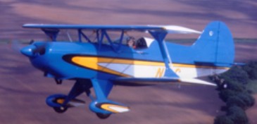
EAA Super Acro-Sport
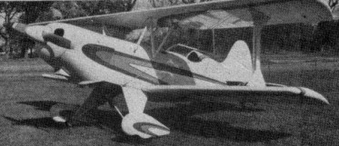
This further development of the Acro-Sport is intended for unlimited international-class aerobatic competition. Though basically similar in appearance to its counterpart, the Super Acro-Sport takes advantage of a more powerful engine turning a fixed-pitch prop, an improved roll rate and inverted flight capabilities. Its two wings have almost sym¬metrical airfoil sections. Also added was a trim tab on the starboard elevator and a servo tab on the port side.
Engine 200-hp Lycoming.
Gross Wt. 1350 lb.
Empty Wt. 884 lb.
Fuel capacity 20 USG
Wingspan 19 ft 7 in
Length 17 ft 6 ft
Top speed 156 mph
Cruise 135 mph
Stall 50 mph
Climb rate 3700 fpm
Ceiling 15,000 ft
Takeoff run 125 ft
Landing roll 800 ft
Range 300 miles
EAA Acro-Sport II
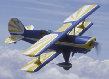
The Acro II, a two-place larger version of the single-place Acro Sport, can be constructed for little more than its single-place brothers. With its larger wheels, wide landing gear and light gross weight, the Acro II is a fun, docile sport airplane designed for engines ranging in power from 115 to 200 hp. When fitted with a 180-hp Lycoming, its empty weight of 875 pounds. First flown on 9 July 1978, like all Acro Sports, its cockpit is designed to be comfortable for pilots up to 6 ft 6 in and 240 pounds. The airframe is larger than the really “midget” biplanes to avoid “touchy” flight characteristics and allow for more baggage. Designed by Paul Poberezny, the Acro II features an M-6 airfoil with a 43-inch chord.
As with all Acro Sport projects, the fuselage is welded steel tube, wings are spruce and Stits Poly-fiber is used for covering. An excellent aerobatic trainer with responsive controls and docile straight and level flight characteristics. Cruise at 123 mph (180 hp), stall at 53 and max out at 152.
I fly N400GB, an Acro II ser# 573.
Daniel Reed
Aug 2022
Engine: Lycoming O-360, 180 hp.
HP range: 115-180.
Speed max: 152 mph.
Cruise: 123 mph.
Range: 300 sm.
Stall: 53 mph.
ROC: 1200 fpm.
Take-off dist: 350 ft.
Landing dist: 800 ft.
Service ceiling: 25,000 ft.
Fuel cap: 26 USG.
Weight empty: 875 lbs.
Gross: 1520 lbs.
Height: 6.7 ft.
Length: 18.85 ft.
Wing span: 21.67 ft.
Wing area: 152 sq.ft.
Seats: 2.
Landing gear: tail wheel.
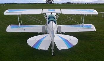
EAA Acro-Sport
This biplane was designed by EAA President Paul Poberezny who wanted to come up with a plane that could be used in high school industrial arts programs and Civil Air Patrol groups as an educational tool. The first flew in January 1972, less than 12 months after the design was started. The Acro-Sport can be fabricated with tools normally found in a high-school shop. It is built with steel tube covered by fabric and 100- to 200-hp engines.


Engine: Lycoming IO-360, 180 hp.
Speed max: 152 mph.
Cruise: 130 mph.
Range: 350 sm.
Stall: 50 mph.
ROC: 3500 fpm.
Take-off dist: 350 ft.
Landing dist: 800 ft.
Service ceiling: 25,000 ft.
HP range: 85-200.
Fuel cap: 20 USG.
Weight empty: 739 lbs.
Gross: 1350 lbs.
Height: 6 ft.
Length: 17.5 ft.
Wing span: 19.7 ft.
Wing area: 116 sq.ft.
Seats: 1.
Landing gear: tail wheel.
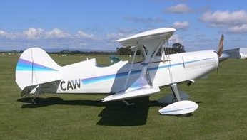
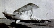
EAA A-1 Biplane
In 1955, the EAA decided to develop a single-seat sport biplane as a service to its members. The prototype was built as a classroom project by students of St.Rita’s High School in Chicago. It flew for the first time on 10 June 1960. The E.A.A. Biplane was designed in response to many requests from members of the American Experimental Aircraft Association for a single seater sports biplane of simple yet rugged construction. The fuselage consists of a welded chrome-moly steel tube frame, to which are fitted plywood formers and wooden stringers, the whole being fabric covered apart from the aluminium coaming panels. Both upper and lower wings have solid spruce spars and built-up wooden ribs, and are internally and externally wire braced. The leading edge to the front spar is aluminium covered, the remainder being fabric covered. Interplane and centre section struts are made of streamline steel tube. A 9.5 Imp. gallon fuel tank is fitted behind the firewall. The empennage, like the fuselage, is built up of welded steel tube and is fabric covered and externally braced. The ailerons which are installed on the lower wing only, are operated by means of push rods, while the elevator and rudder are cable operated. The main undercarriage is built up of steel tube with bungee cords for shock absorption.
Engine: Continental C-85, 85 hp.
Wing span: 20 ft 0 in (6.1 m).
Wing Area: 108 sq. ft.
Wing Loading: 9.4 lb./sq.ft.
Length: 17 ft 0 in (5.18 m).
Height: 6 ft 0 in (1.83 m).
Max TO wt: 1150 lb (522 kg).
Empty Wt. 640 lb.
Fuel capacity 12 USG.
Max level speed: 125 mph (201 kph).
Stall mph 55.
Climb rate 800fpm.
Takeoff run 500 ft.
Landing roll 550 ft.
Range 200 sm.
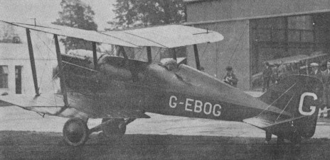
DW Aviation DW.II
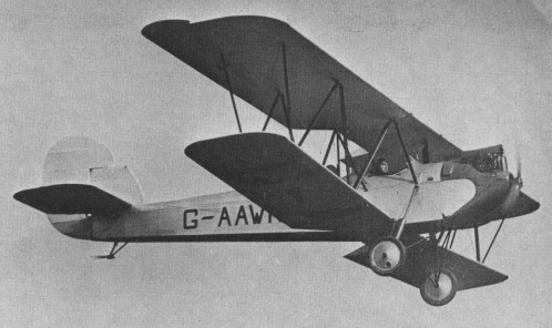
During 1929, Dudley Watt was approached by T. Neville Stack who had an idea for a slow landing, safe -flying training biplane combining the advantages of folding wings with natural stability. Watt agreed to finance the construction and formed a company, D. W. Aviation Co, at Brooklands. The aircraft was designed by Captain K. N. Pearson, M.C., AFRAeS, and dubbed the D.W.II. By the end of 1929, first wood had been cut. Drawings for the tail unit were completed by March 1930 from which time forward construction proceeded at full speed. .
The work team consisted of Bill Hellon, a former Handley Page general mechanic who had worked with Savage Skywriters at Hendon, and Bill Whitaker, an aircraft craftsman who had formerly worked for both Vickers and Hawkers. The chief engineer responsible for the project was William A. Baker.
The building of the D.W.II took place in the “black sheds” at Brook¬lands and on May 17, 1930, G AAWK made its public debut in the hands of Dudley Watt. The engine was a 90 h.p. ADC Cirrus III.
The D.W.II was an instant success.
Everything seemed set fair for this biplane with its “unusually high lift” wings which cruised at a respectable 75 m.p.h. on such comparatively low power.
It was at this point that the whole enterprise left Brooklands for Ford Aerodrome, Yapton, Sussex, where larger hangars were available. Here was to be set up a production line.
But things did not work out as planned and the Dudley Watt fortunes took a turn for the worse. Inspired by the success of the D.W.II, work had already begun on the mock up of a three seat version to be known as the D.W.III. This was never to be and just before Christmas, 1930, the collapse came. In spite of its success, orders did not materialise for the D.W.II and there was now no cash left to allow speculative building. Dudley Watt was forced to sack his workforce.
Watt and the D.W.II turned up at aviation meetings during the following season but afterwards gradually faded from the aviation scene. The D.W.II was sold in 1934 to Brian Field who dismantled it into oblivion.
DW Aviation DW.I
The Aircraft Disposal Co Ltd was selling off refurbished ex RAF SE.5s. Inspired by the potential of the S.E.5a just as had McCudden and others before him, Dudley Watt rebuilt his machine as a high perform-ance model. The 200 h.p. Wolseley Viper was replaced by a 300 h.p. Hispano Suiza enclosed in a stream-lined cowling and cooled by under¬slung radiators. The rear fuselage decking was redesigned to fair in with the pilot’s headrest and a smaller windscreen was fitted. Now named the D.W.l., the work on this Hisso–powered hybrid was carried out in a shed at Brooklands near the old Henderson School of Flying hangars.
Dudley Watt raced it as a standard S.E.5a at Bournemouth in April 1927. In its re vamped form it should have been a race winner but records do not show it to have been a flag dropper. The D.W.1 was finally burned at Whitchurch in 1932.
Dusenbury Wright Flyer III
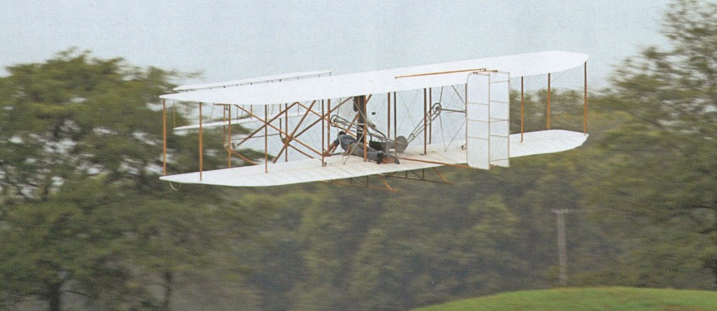
On October 3, 2007, at Huffman Prairie, Ohio, USA, Mark Dusenberry flew his Wright Flyer III reproduction for 2min 10sec around the oval course where Wilbur Wright proved the practicality of powered flight in 1905.
Dusenberry’s flight was the longest achieved by a Wright III reproduction. It came during rehearsals for a series of educational events on October 5 to celebrate the 102nd anniversary of Wilbur’s flight, during which the pioneer flew 29 laps of the course, covering 24 miles in 39min.
Construction took Dusenberry 10,000hr over a 10yr period, using the same materials seen on the original, spruce and ash. He also built a reproduction 1905 engine, and carved the spruce propellers. The only departure from original construction was the polyester cloth covering.
The October 5 events were organised by the US National Parks Service, and 2,500 people assembled at the prairie to watch Dusenberry’s flight; it lasted only 40sec, ending when the starboard wingtip clipped the ground in a turn. Mark was unhurt in the impact, and said. “All I broke was a bunch of sticks, and put a few holes in the fabric. I will repair it, and should have it flying in about a year”
