Grigorovich M-2 / M-3 / M-4 / Shchetinin M-2

Despite the poor results obtained with the M-1 flying boat, the Russian fleet command was predisposed towards an effective national flying boat model. On June 28, 1914 , the Naval General Staff (MGSh) wrote:
“The General Staff… to get out of the position, considers it very advisable to start the indigenous construction of hydroplanes and establishes the following conclusions:
1 – Because the hydroplane designed and built at the SS Schetinin and K Society is available, allowing the factory to carry out the tests at the Puerto del Emperador Alexander III aviation station, but on the condition that the pilot be from the factory. In case of success of the tests the flying boat will be acquired for the needs of the Baltic Sea aviation.
‘ In the event that the hydroplane shows good results, the Naval General Staff considers requesting several of these boats after the problems presented have been solved.”

On the other hand, with the war approaching, the Navy leadership, the 2nd rank captain BP Dudorov requested the MGSh without delay to buy from the PRTV and the RBVZ (Russian Baltic Wagon Factory) all the hydrofoils, finished or not, that could be ready in a short period of time.

These factors encouraged Schetinin to redirect the fundamental activity of PRTV towards the development of navalized models. DP Grigorovich was working on a development of the M-1 model, so on July 29, 1914 a contract would be signed for the production of four new improved examples.

The changes introduced were so significant that the resulting aircraft earned the right to be defined as a new model, which came to light as the M-2 (Morskoi (Naval) – 2), Russian: Григорович М-2.

The contract established the delivery of the first copy for the 7th, the second for the 12th, the third for the 17th and the last for August 23, 1914. Each flying boat was valued at 8,000 rubles and instructions were given to collect four GnĂ´me engines between 80 and 100 hp in Moscow.

The acceptance conditions established the reach of a height of 500 meters in 12 minutes with the 100 hp engine and 15 minutes with the 80 hp, carrying a load of 75 kg above the weight of the crew and the necessary fuel for three flight hours.

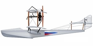
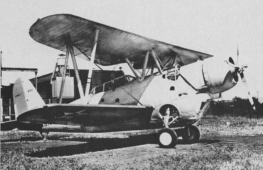
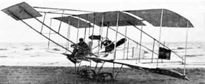
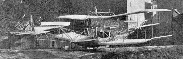
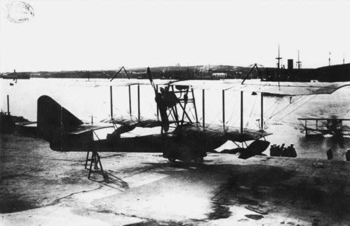
The M-2 was a propeller-driven biplane flying boat, generally similar to that of the M-1 and originally the same engine, but its overall dimensions were increased. The hull grew in width in order to accommodate both crew members side by side. The bow also changed its shape from flat to tapered with a concave bottom in the front, while a new three-sided tail section featured new, much higher mounts, to which the considerably larger area stabilizer was attached.

The wingspan of the upper wing was considerably greater than that of the lower wing, but unlike the M-1 the diagonal supports at the wingtips were not used. The biplane box maintained its location on supports above the fuselage and had only large-area ailerons on the upper plane. The lower wings were installed 1m above the hull on the engine support frame.

The triangular section rear fuselage was raised from the water, tail was equipped with a skid, often referred to as the “shovel”.

According to Shavrov the M-2 to M-4 were used to test some novelties such as the variable incidence stabilizers in flight (for this purpose they had an elevator in the lower part of the leading edge) and in the M-4 a ski – paddle with rubber buffer hinged under the tail to improve launch.

The types of wood used were generally similar to those used during the construction of the M-1.

The construction of the model in the Schetinin factory introduced a constructive novelty: for the first time in Russia, the hull was formed inverted, with the keel up. The first M-2 was delivered to the naval experimental station located in the Grebni port of Petrograd only on August 18, 1914, because before that date the hangar was not found ready for its conservation.

The tests of the prototype with the 80 hp GnĂ´me engine plant began in August 1914. Unfortunately, the prototype was destroyed on the 31st of that month causing the death of its pilot PV Evsyukov. It is noteworthy that VB Shavrov defines this engine as an 80 hp Clerget, which makes this statement appear in multiple articles and sites that reference this source.

The construction of the other examples was stopped until the investigations were completed. The causes of the accident were never established, but no problems related to structural weaknesses or linked to the construction of the model were found, so it was agreed to continue production.

On October 8 at the Schetinin factory, 4 GnĂ´me Monosoupape engines of 100 hp were received (The engine of the damaged unit was delivered to the RBVZ) and on November 28, 1914 the first of the new units with this power plant and modifications in the selection of the airfoil was received at the Third Naval Station in Revel (Tallinn). Only 12 days later a second copy would arrive. The test flights were developed until December 22 by the pilot of the factory Ya. I. Siedov-Sierov and the fleet pilot Lieutenant II Kulniev, resulting in numerous remarks and proposals for improvements.

On December 20 three FBA (Franco-British-Aviation) flying boats of the six contracted to France on September 12, 1914 arrived at the Third Station. Both because of their construction and because of their performance, they were quite superior to the M-2, which is why the representatives of the Navy took a negative position towards the Schetinin – Grigorovich model. By the end of the year none of them had been able to present themselves to the acceptance tests.

During the winter the company’s mechanic and pilot made the changes so that by the spring of 1915 flights could be resumed. At that time, a series of improved components arrived from the factory and were installed in the second prototype. General tests continued until April 1915, resulting in a climb time of 15 minutes to a height of 1,300 meters.

The third flying boat Đś-2 code Sch-3 in the fleet register, with Lieutenant VA Litvinov, head of the Kilkond naval station in the cabin.

In general, they received a positive assessment, so on April 25, 1915 they entered service with the Baltic Fleet aviation with the registrations Sch-2 and Sch-3. These served in the Third Revel Station, basically in training missions, until they were discharged in the winter of 1915-1916 (in the month of November according to Maslov). After that date the engines were removed and for some time were kept in Revel. Due to the fact that these examples underwent changes in the wing profile and hull lines during the tests, their name was changed to M-3 (according to Maslov the name M-3 only corresponded to the second of these, since the first kept as M-2 (Sch-2)).

In the summer of 1914 in the Black Sea the situation was calm and by the month of September the Naval Aviation only had six military planes. The situation would change radically in October, when Turkey declared war on Russia. The new situation made it necessary to take urgent measures.

M-4 number 29, belonging to the Black Sea fleet

From a request of the Black Sea pilots and after several talks held by the head of the Russian aviation, Grand Prince Alexander Mikhailovich Romanov, the commander of the Baltic Fleet NO von Essen; the head of the MGSh AI Rusini and the head of the Aeronautical Department of the MGSh AA Tuchkov, the remaining two copies of the contract of four were sent to Sevastopol on March 10, 1915. This measure was aimed at strengthening the capacity of the air forces for the operations to be carried out in the Bosphorus area.

Ten days after the arrival, a PRTV brigade would arrive under engineer AN Sidielnikov and also made up of pilot Ya. I. Siedov-Sierov, two mechanics and two assemblers. On March 24 the flying boats were transferred to the assembly site and on the 31st the commission from the port of Sevastopol arrived to carry out the tests.

They had to make a flight of 25 minutes and another of 13 minutes in which they should reach the contracted height in 7.5 minutes. The planes received the numberings “29” and “30” and were to complement a varied group of seaplanes that made up the Black Sea Fleet aviation. These M-2s would later be referenced in documents as M-2/M-4 or simply M-4.

M-4 number 29

On April 8, 1915, military pilots began familiarization flights and after a series of acceptance tests, the two were accepted by the Fleet, eventually being used in military actions. On April 12, 1915, number 29, armed with a Maxim machine gun in an installation designed by Kryltsov, was lowered into the water from the cruiser “Emperor Nikolai I” in the Bosphorus region. Crewed by A. Ye. Zhukov and SN Korsakov the flying boat managed to carry out an attack on a Turkish gunboat of the type “Burak Reis”, dropping a bomb that exploded about 70 meters from the stern. This was considered the first military action of a flying boat in Russia and could have ended as a major catastrophe: a hose rupture forced the crew to make a landing a considerable distance from the base, but they managed to reach it by sailing.

Reports on the use of the Schetinin / Grigorovich flying boats in the Black Sea theater were promising, but the Aviation Committee had some doubts about the structural resistance of the model, especially since “30” began to present problems with the hull cladding slats, which came off even after normal landings. As a result, on May 15, a document was issued to the factory in which it recommended reducing the angle of attack of the stabilization floats, reinforcing their fixation and modifying the hull in order to add a rudder that would improve operation in the water. PRTV received the considerations but there was little that could be done because the production had culminated with the delivery of the four copies.

The flying boat “30” was decommissioned in October 1915. In the case of “29”, no evidence has been found to define its operating time.

The factory numbers of the delivered were 196 and 197 (the numbers of the others are unknown), The Baltic Sea Fleet of M-3s were Sch-2 and SCh-3. The Black Sea Fleet of M-4s were naval register ”29”, factory number 196, and naval register ”30”, factory number 197.

M-2 prototype
Powerplant: 1 x 80 hp GnĂ´me
Upper plane wingspan: 13.68 m
Wing area: 33.5 m²
Length: 8.0m
Normal takeoff weight: 870 kg
Wing loading: 26 kg/ m²
Power Load: 10.9kg/hp
Speed at sea level: 115km/h
Cruising speed: 76km/h
Ascent time to 1000 m: 7 min
Ceiling: 4000m
Practical range: 320 km
Endurance: 3.5 hours
Accommodation: 2 side by side

1913 M-3
Span: 44’10”
Length: 26’3″
Loaded Weight: 1918 lb

M-4
Powerplant: 1 x 100 hp Gnome Monosoupape
Wingspan: 13.62m
Wing area: 37.90 m²
Length: 8.00m
Normal takeoff weight: 870 kg
Wing loading: 26 kg/m²
Power load: 8.7kg/hp
Top speed: 100km/h
Cruising speed: 76km/h
Practical range: 320 km
Accommodation: 2 side by side

Grigorovich M-2

Griffon Lionheart

Developed for flying enthusiasts as a “kit” aircraft and designed to make the building process pleasant, fun, and memorable, the Lionheart is an elegant and spirited, 220+ mph, six place, long-distance cruiser. Its design is inspired by the classic Beech Staggerwing and features a fuel capacity of 180 gallons with a range of around 1450nm, payload around 2,000 pounds, and stall characteristics in the mid-fifty knot range. The aircraft’s primary structure consists of high-temperature glass and carbon composites molded in precision production tooling. Lionheart’s powerplant is the reliable and powerful 450HP Pratt & Whitney R-985 Wasp Jr. Radial engine.
The fuselage is about 20 feet long from firewall to rudder post making Lionheart a cabin class aircraft that can be constructed in a relatively small space. Interior cabin volume and seating is similar to the Malibu but wider at the shoulders. A small aisle exists between the first two rows of seats and cabin access/egress is via a single split door between the mid and rear seats on the left side of the fuselage (ala Malibu and Staggerwing).

Lionheart accommodates 6 full size, FAA 170 lb passengers and is designed with a 5200 lb gross weight at +6,-3 G limit loads. Following structural testing the gross weight is increased for +4.4, -2.2 G limit loads (utility category). With an estimated empty weight of 3100 to 3300 lbs, Lionheart has a payload of about 2000 lbs. Just about right for the wife and kids… and lots of fuel.
Dual control sticks are designed for the pilot and co-pilot seats. Ailerons and elevator are pushrod actuated while the rudder is cable operated. The four ailerons and flaps of the upper and lower wings are interconnected at the wing roots via cables. With the exception of the landing gear attachment fittings, the upper and lower wings are identical.
Lionheart uses a fully retractable conventional (taildragger) landing gear. The mains use pressurized gas for spring and damping while the tailwheel is sprung via a gas charged air/oil cylinder. Retraction is accomplished using electro-hydraulics. Landing gear track and wheelbase are both wider and longer than the stock Staggerwing, so ground handling is improved.
Lionheart prototype N985L flew for the first time Sunday morning, July 27, 1997.

Chuck Cianchette of Palmyra, Maine, built the first customer-built Lionheart, first flying in 2000.

Chuck Cianchette

In 2009 the Lionheart was out of production.

Top speed: 230 mph
Cruise: 210 mph
Stall: 56 mph
Range: 1500 sm
Rate of climb: 2500 fpm
Takeoff dist: 800 ft
Landing dist: 1400 ft
Service ceiling: 20,000 ft
Engine: Pratt & Whitney R-987, 450 hp
HP range: 350-600
Fuel capacity: 160 USG
Empty weight: 2900 lb
Gross weight: 5200 lb
Height: 8 ft
Length: 26.6 ft
Wing span: 31 ft
Wing area: 238 sq.ft
Seats: 7
Landing gear: retract/tail

Engine: Pratt & Whitney
Wing span: 9.45 m
Wing area: 21.9 sq.m
MAUW: 1905 kg
Empty weight: 1043 kg
Fuel capacity: 530 lt
Max speed: 370 kph
Cruise speed: 322 kph
Minimum speed: 98 kph
Climb rate: 15 m/s
Seats: 6
Fuel consumption: 12 lt/hr
Kit price (1998): $89,900

Great Lakes XTBG-1

This three-seat biplane was Great Lakes entry in the torpedo bomber competition which ended with the adoption of the Devastator. It was the last biplane considered by the US. Navy for that role.

The XTBG-1 featured a small independent front cockpit placed just behind the engine which was employed by the “torpedoman.”

With its top speed of 200 mph, the Devastator bested it easily.

Only the prototype was built.

Great Lakes 2T

2T-1A-1

The original Great Lakes Model 2T-I Sport Trainer was built by the Great Lakes Aircraft Corp. in Cleveland, Ohio, in 1929.
Between 1929 and 1932, the company built more than 200 of them, and they quickly became a great favorite of aerobatic pilots. The designer, Charles W. Meyers, raced a customized Great Lakes with considerable success during the early 1930s, and the legendary Tex Rankin flew one in airshows throughout the country before World War II setting records for both inside and outside loops. After the war, enthusiasm for the airplane continued and many airframes were converted to accept larger engines, particularly Warner radials. During the past several years, factory blueprints of the design have been available to homebuilders from the resurrected Great Lakes Aircraft Co., also of Cleveland, and several are under construction utilizing various modern engines.
The 2T 1 began as a very simple, clean design with straight wings and a four cylinder 85 hp Cirrus engine. It was found to be tail heavy and accordingly difficult to recover from a flat spin. For some reason reluctant to move the engine forward, the designers hit upon the expedient of moving the center of lift aft by sweeping back the outer panels of the top wing. This decision was fortuitous; it wasn’t clearly realized at the time, but sweeping the wings of an airplane tends to improve its snap rolling ability.
First shown in Detroit in 1929, the 2T 1 was an instant success, winning 500 orders from prospective dealers within a couple of weeks of its debut. Bringing in consultants from the auto industry, the Great lakes Air¬craft Company set up a Detroit style production line. The airplane was certificated in June 1929; aided by tours, publicity stunts and some surprising success as a racer, the 2T 1 promised to make the fortune of its builders but then October came, and the stock market crash, and the future changed completely. Production went on into the spring of 1931; thereafter, airplanes were built to order from parts backlogs, but series manufacture ceased.
The original upright Cirrus engine eventually was replaced with an inverted, or “Hi Drive,” Cirrus of 90 hp; but none of the Cirrus engines was entirely satisfactory, and surviving airplanes were eventually reengined, many of them with radials such as the 145 hp Warner Scarab and the 185 hp.
About 1964, Harvey R. Swack decided it was a shame that the city of Cleveland (home of the original Great Lakes Company) had forgotten Great Lakes. What the local museum needed was a restoration or a replica of the 2T 1. The museum agreed. Unable to afford the genuine article, Swack determined to build a replica. He obtained from the FAA a copy of the original blueprints, but then some involved legal obstacles to his building the replica arose, and he was obliged to search out the legal owners of the design and the type certificate.
Then the museum decided it would not settle for a mere replica. But now Swack, who had visited the Great Lakes factory as a boy and who treasured a memory of the sporty maroon biplane on display there, set out to render the fine old machine its due first by selling copies of the blueprints to homebuilders, paying a commission to the legal owners, and eventually by buying the title to the design. The type certificate had expired, but Swack managed to extract a renewal from the FAA and began to dream of getting the airplane back into production.

Doug Champlin was an airplane collector who had run an operation re¬storing Waco UPF 7s but when the supply of Waco basket cases ran out, Champlin cast about for another approach and came upon Harvey Swack. Swack sold out to Champlin, who first equipped the airplane with a 140 hp Lycoming engine and then got an entirely new type certificate for a four aileron version with a 180 hp engine and constant speed prop, cleaning up the old certificate, which with the addition of modern engine and prop, new inverted systems and fuel tanks, wing mods and heel brakes had become an unwieldy thicket of STCs.
The new Great Lakes, built in Wichita and Enid, Oklahoma, first came out in 1972.
In 1973, the Model 2T-IA-1 was certified with a 140-hp Lycoming, and the Model 2T-IA-2 (with a 180-hp Lycoming) was produced for the first time in 1974.
By 1977 was building airplanes at the rate of three a month. The company has drawn a lot of attention at air shows with a special display airplane powered by a 420 shp Allison turboprop. This airplane is not in-tended for production; it is more a cooperative demonstration of capability by Great Lakes and Allison.
In 1980, after more than 50 years, the legendary Great Lakes biplane found a new home in Eastman, Georgia. R. Dean Franklin, a Great Lakes pilot, set up a modern
production facility after acquiring production rights, type certificates, and other assets of the Great Lakes Aircraft Co. The Great Lakes is the oldest certificated airplane still in production, and its manufacture closely follows the basic specifications of the original design.
The Great Lakes production ended in 1978. The manufacturer of the 1930s design, two seat sport biplane, which has delivered 126 of the airplanes since production was resumed in 1973, will continue to produce spare parts for the aircraft in service.

Great Lakes 2T-1A NC842K s/n 106

(1932)
Engine 90-hp Cirrus.
Seats 2.
Gross wt. 1,580 lb.
Empty wt. 910 lb.
Top speed 116 mph.
Cruise 100 mph.
Stall 40 mph.
Initial climb rate 1,035 fpm.
Range 400 nm.
Ceiling 21,000ft

Engine 180-hp Lycoming
Seats 2.
Gross wt. 1,800 lb.
Empty wt. 1,230 lb.
Fuel capacity 26 USG
Top 132 mph.
Cruise 118 mph.
Stall 54 mph.
Initial climb rate 1,150 fpm.
Ceiling 17,000 ft.
Range 300 nm.
Takeoff distance (50′) 825 ft.
Landing distance (50′) 825 ft.

2T-1
Engine: AC.E. Cirrus, 95 hp.

2T-1A
Engine: 140 hp.

2T-1A-2
Engine: Lycoming AEIO-360-B1G6, 180 hp.
TBO: 1800 hrs.
Prop: Hartzell 2-blade, 74-in.
Seats: 2.
Length: 21.1 ft.
Height: 7.7 ft.
Wingspan: 26.7 ft.
Wing area: 180 sq.ft.
Maximum ramp weight: 1800 lbs.
Maximum takeoff weight: 1800 lbs.
Standard empty weight: 1230 lbs.
Maximum useful load: 570 lbs.
Maximum landing weight: 1800 lbs.
Wing loading: 10 lbs/sq.ft.
Power loading: 10 lbs/hp.
Maximum usable fuel: 150 lbs.
Best rate of climb: 1150 @ 65 kts.
Climb gradient: 1061 ft/nm.
ROC @ 8000 ft: 683 fpm.
Service ceiling: 17,000 ft.
Maximum speed: 110 kts.
Normal cruise @ 65% pwr @ 8000 ft: 102 kts.
Fuel flow @ normal cruise: 48 pph.
Endurance at normal cruise: 3 hrs:
Stalling speed clean: 48 kts.
Stalling speed flaps down: 46 kts.
Turbulent-air penetration speed: 133 kts.

2T-1R

2T-4A 2
Engine: Lycoming IO 360 B1F6, 180hp.
Length: 20 ft. 4 in.
Height: 7 ft. 4 in.
Wingspan: 26 ft. 8 in.
Wing area: 187.6 sq. ft.
Seats: 2.
Gross weight: 1,800 lbs.
Empty weight: 1,230 lbs.
Useful load: 570 lbs.
Payload with full fuel: 414 lbs.
Fuel cap: 26 USG/156 lbs.
Wing loading: 9.63 lbs./sq.ft.
Power loading: 10 lb/hp.
Minimum field length: 850 ft.
Rate of climb: 1,400 fpm.
Maximum cruise (75% power): 105 kts.
Economy cruise (55% power): 92 kts.
Range at Maximum cruise, 45 min res: 208 nm.
Range at economy cruise, 45 min res: 242 nm.
Stall speed: 47 kts.
Service ceiling: 17,000 ft.

2000 Great Lakes
Engine: Lycoming IO-360-B1F6, 180hp
TBO: 2000 hrs
Fuel type: 100/100LL
Propeller type: Hartzell CS
Landing gear type: Conventional/Fixed
Max ramp weight: 1800 lb
Gross weight: 1800 lb
Landing weight: 1800 lb
Empty weight, std. : 1230 lb
Useful load, std.: 570 lb
Payload, full std. fuel: 414 lb
Usable fuel, std: 26 USG
Wingspan: 26 ft. 8 in.
Overall length: 20 ft. 4 in.
Height: 7 ft. 4 in.
Wing area: 188 sq. ft
Wing loading: 9.6 lbs./sq. ft.
Power loading: 10.0 lbs./hp
Wheel track: 5 ft. 9 in.
Wheel size: 6.00 x 6 in
Seating capacity: 2
Baggage capacity: 30 lb
Cruise speed 75% power @ 6,000 ft.: 101 kt
Max range (w/ reserve) 55% power: 310 nm
Estimated endurance (65%): 2.5 hr
Stall speed: 47 knots
Best rate of climb: 1150 fpm
Service ceiling: 17,000 ft
Takeoff ground roll: 575 ft
Takeoff over 50-ft. obstacle: 825 ft
Landing ground roll: 400 ft
Landing over 50-ft. obstacle: 825 ft

Great Lakes Sport Trainer
Top speed: 138 mph
Cruise: 125 mph
Stall: 40 mph
Range: 340 sm
Rate of climb: 1200 fpm
Takeoff dist: 300 ft
Landing dist: 400 ft
Service ceiling: 14,000 ft
Engine: Lycoming O-320, 150 hp
HP range: 125-200
Fuel capacity: 26 USG
Empty weight: 1025 lb
Gross weight: 1618 lb
Height: 7.3 ft
Length: 20.3 ft
Wing span: 26.7 ft
Wing area: 187.5 sq.ft
Seats: 2
Landing gear: tail

Grant Albatross D.5

Tom Grant designed and built his 3/4 scale Albatross D V replica from his own plans over about 14 years, which included a building time of around three and a half years.

The fuselage was built up from white pine carvel planking (a boat building technique), with a lightweight fibreglass finish. The wings are of standard spruce spars and ribs with fabric covering. The engine is a 4 cylinder Toyota 480E from a Corolla.

ZK-DVR (c/n TG01) was registered to Tom Grant of Dunedin on 8 November 2007. Tom says that it flies just like it is supposed to, and he had flown around 50 hours.

On 26 October 2015 it was reported;
Witnesses to the emergency landing of a replica World War 1 fighter heard the plane coughing before a loud ”boom” gave way to silence as it descended on to a ridge high above Ocean View on Saturday.
Police lauded the quick-thinking pilot for his ”perfect” emergency landing of the three-quarter Albatros D.Va replica on farmland above Brighton Rd about 10.50am.
The pilot, Tom Grant (87), was fine despite the plane hitting a fence on a ridge about 100m above Brighton Rd during the emergency landing, his wife, Jeanette, said.
”It was a controlled landing. He just caught the top of the wire as he came in,” she said.
”He got a tiny bump on his nose … but he’s fine.”
It appeared the landing buckled the plane’s wheels and damaged the right wing and undercarriage.
The plane, which Mr Grant built, was salvageable and would be ”next winter’s project”, Mrs Grant said.