Engine: 1 x 583hp Bristol Jupiter 9-cylinder air-cooled radial engine Max take-off weight: 2568 kg / 5662 lb Empty weight: 1488 kg / 3280 lb Wingspan: 14.10 m / 46 ft 3 in Length: 9.02 m / 29 ft 7 in Height: 4.06 m / 13 ft 4 in Wing area: 46.15 sq.m / 496.75 sq ft Max. Speed: 217 km/h / 135 mph Ceiling: 6096 m / 20000 ft Crew: 2
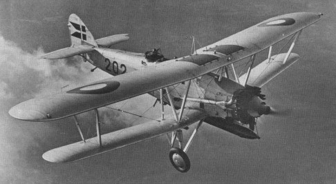
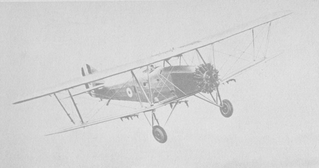
Basically Hawker Horsleys with their 665 hp Rolls Royce Condor engines replaced by 800 hp Armstrong Siddeley Leopard IIs, two Dantorps were ordered from Hawkers by the Danish Government in 1930, pending licenced production by the Danish Naval Dockyard factory at Copenhagen. Both aircraft were to have alternative wheel and float undercarriages. Of composite wood and metal construction, the Dantorp differed from the Horsley in having a third crew member between the pilot and observer/gunner. The first aircraft, 201, made its first flight at Brooklands on September 19, 1932, piloted by “Gerry” Sayer. The second machine, 202, flew shortly afterwards and, in November 1932, was tested on its float undercarriage at Felixstowe. Before delivery both aircraft were re engined with the 805 hp Leopard IIIA. Licensed production of the type was not taken up, however, though the two Hawker built originals flew extensively with the Royal Danish Naval Air Service from 1933 onwards.
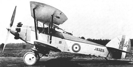
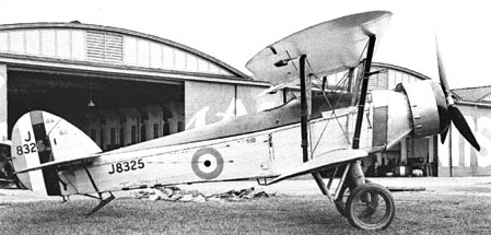
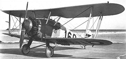
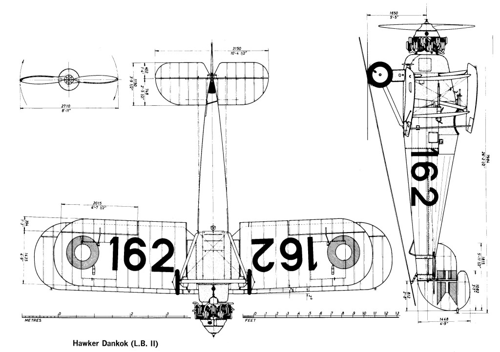
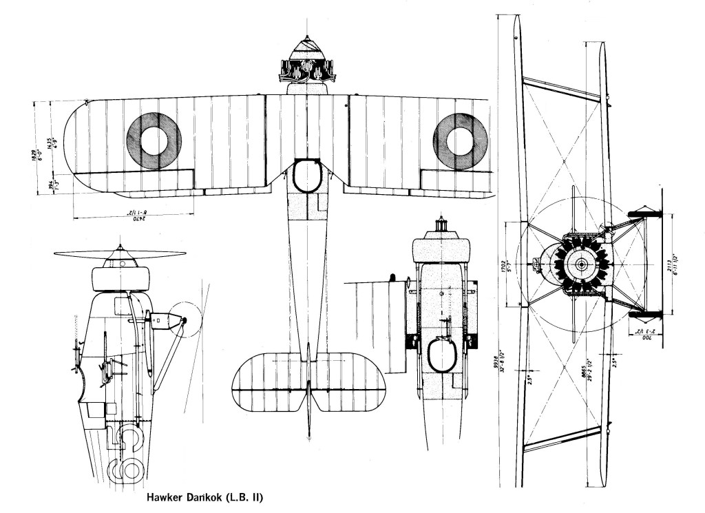
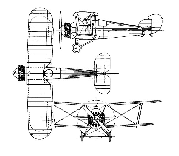
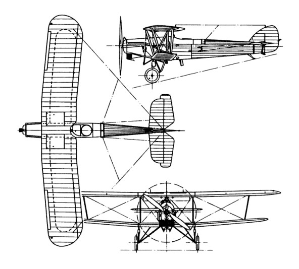
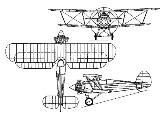
Based on the Woodcock II and designed by Sydney Camm, the Danecock was developed to meet a requirement of the Danish Naval Air Service, or Marine Flyvevaesenets. By comparison with the Woodcock II, the Danecock (Dankok) had unequal span wings, a slightly lengthened fuselage, a 385hp Armstrong Siddeley Jaguar IV engine and an armament of two 7.7mm Madsen machine guns. The first of three Danecocks ordered from the parent company was flown on 15 December 1925, and the licence manufacture of a further 12 was undertaken by the naval dockyard (Orlogsvaerftet) during 1927-28. They were fitted with 2 blade Danish Orlogsvaerftet wooden propellors.
With serials 155-165, they served from January 1926 until the German occupation in April 1940 as the Hawker Dankok (LB.II for Land Biplane Type 2). A single Dankok (165) was experimentally fitted with a streamlined ownsend Ring which raised the top speed from 235 kph/148mph to 245 kph/152mph.
Max take-off weight: 1381 kg / 3045 lb Empty weight: 965 kg / 2127 lb Wingspan: 9.92 m / 32 ft 7 in Length: 7.96 m / 26 ft 1 in Wing area: 31.59 sq.m / 340.03 sq ft Max. speed: 233 km/h / 145 mph Cruise speed: 169 km/h / 105 mph
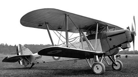
Representing an attempt to design the smallest and lightest practical airframe around the most powerful available engine suitable for fighter installation, the Hornbill was built to Specification 7/24 and flown in late summer 1925. Of mixed construction, with a duralumin-skinned steel tube forward fuselage and fabric-covered rear fuselage, wings and tail surfaces, the Hornbill was at first powered by an 826hp Rolls-Royce Condor III eight-cylinder water-cooled inline engine with twin radiators under the lower wing. In May 1926, it flew with a 698hp Condor IV and a single ventral radiator. It possessed an armament of one 7.7mm Vickers Mk 2 machine gun. The Hornbill was the fastest armed aircraft to have been tested by the RAF when it commenced service evaluation at Martlesham Heath in late 1925, but rate of climb and service ceiling were poor and some handling aspects unsatisfactory. No production order materialised.
Max take-off weight: 1732 kg / 3818 lb Empty weight: 1349 kg / 2974 lb Wingspan: 9.45 m / 31 ft 0 in Length: 8.11 m / 26 ft 7 in Height: 2.95 m / 9 ft 8 in Wing area: 29.49 sq.m / 317.43 sq ft Max. speed: 301 km/h / 187 mph Cruise speed: 220 km/h / 137 mph Ceiling: 6920 m / 22700 ft
Built as a private venture, the Heron single-seat fighter was the first of the Hawker company’s fighters to have a predominantly metal structure. A single-bay biplane with provision for two 7.7mm synchronised Vickers guns, the Heron was built up of round steel and aluminium tubing bolted together (rather than welded) and braced by high-tensile wires. The prototype, initially flown early in 1925, was highly praised during official trials at Martlesham Heath in 1926 but was subsequently returned to the manufacturer by which it was flown until mid-1928.
Take-off weight: 1418 kg / 3126 lb Empty weight: 962 kg / 2121 lb Wingspan: 9.70 m / 31 ft 10 in Length: 6.78 m / 22 ft 3 in Height: 2.97 m / 9 ft 9 in Wing area: 27.03 sq.m / 290.95 sq ft Max. speed: 251 km/h / 156 mph
The Horsley was produced for the RAF as a bomber and torpedo bomber, entering service in these roles in 1927 and 1928 respectively after severe competitive tests against the Westland Yeovil, Bristol Berkeley and Handley Page Handcross. The Greek Naval Air Service also received six in 1928, and it was licence-built in Denmark as the Dantorp (military designation H.M.III). In total 121 Horsleys were built, most powered by 499kW Rolls-Royce Condor IIIA geared engines and with all-metal airframes, although early production aircraft were of wooden and then mixed construction. Apart from its speed and climb, it possessed the manoeuvrability of a scout and the aerodynamic design was such that the machine could be flown ‘hands off’ for periods. Day or night operations were possible.
In 1926 a proposal was made that the RAF should attempt a non-stop flight to India. This would not only be operationally significant, but enormously prestigious to the service if successful. It would at the same time establish a new world long-distance record. The chosen vehicle for this attempt was the Hawker Horsley, then entering RAF service as a day and torpedo-bomber. A production example was modified with strengthened landing gear to carry the additional weight of an extra 3,955 litres of fuel accommodated in new wing and fuselage tanks, an overload of nearly 200% of the structure weight. On 20 May 1927 Flt Lieut C. R. Carr and Flt Lieut L. E. M. Gillman took off for India, only to be forced down in the Persian Gulf after completing 5,504km: a new long-distance record that was beaten in less than 24 hours when Charles Lindbergh landed at Paris after his 5,778km solo flight across the North Atlantic.
The Horsley made three long-distance flights. The first was carried out by Flt Lt Carr as pilot and Flt Lt Gillman as navigator, who had expected to cover more than 6,440km from Cranwell to India. However during 20-21 May 1927 they covered a distance of 5,502km, landing short near Bandar Abbas on the Persian Gulf because of problems with the oil system. A second effort by Carr and Flt Lt Mackworth ended after one hour’s flying; while a third attempt by Carr and Fl Officer Dearth ended in Austria, alighting in the River Danube.
Hawker Horsley – Leopard engine
Engine: 1 x Rolls-Royce Condor IIIA, 496kW / 666 hp Max take-off weight: 3538 kg / 7800 lb Empty weight: 2159 kg / 4760 lb Wingspan: 17.21 m / 56 ft 6 in Length: 11.84 m / 38 ft 10 in Height: 4.17 m / 13 ft 8 in Wing area: 64.38 sq.m / 692.98 sq ft Max. speed: 201 km/h / 125 mph Ceiling: 4265 m / 14000 ft Armament: 2 x 7.7mm machine-guns, 680kg of bombs Crew: 2
The Nimrod was basically the FAA version of the Fury single-seat interceptor fighter. In general arrangement and construction it was almost identical to the Fury and was fitted with a 440kW Rolls-Royce Kestrel IIS supercharged engine (later replaced by the Kestrel V on Mk IIs). It was, of course, strengthened for catapulting and carried more comprehensive equipment and extra fuel. The Nimrod embodied the Hawker-patented system of metal construction, all but the first three stainless steel Mk IIs being built of ordinary steel and duralumin. Apart from simplicity of construction, this system allowed maintenance and repairs, if necessary, to be undertaken by unskilled labour and with the simplest of materials. Armament comprised two forward-firing Vickers machine-guns, plus optional light bombs; equipment included a wireless, oxygen apparatus, hoisting gear and electrical equipment. A total of 54 Mk Is and 27 Mk IIs were produced for the FAA, plus some for export to Japan, Denmark and Portugal.
Nimrod Mk II Engine: 1 x Rolls-Royce Kestrel VFP, 453kW Max take-off weight: 1841 kg / 4059 lb Empty weight: 1413 kg / 3115 lb Wingspan: 10.23 m / 33 ft 7 in Length: 8.09 m / 26 ft 7 in Height: 3.00 m / 9 ft 10 in Wing area: 27.96 sq.m / 300.96 sq ft Wing loading: 13.53 lb/sq.ft / 66.00 kg/sq.m Max. Speed: 168 kts / 311 km/h / 193 mph Cruise speed: 100 kts / 185 km/h / 115 mph Service Ceiling: 8535 m / 28000 ft Endurance: 2 h Armament: 2 x 7.7mm machine-guns, 4 x 9kg bombs Crew: 1
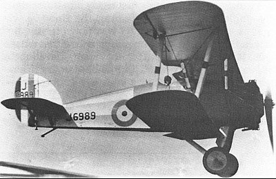
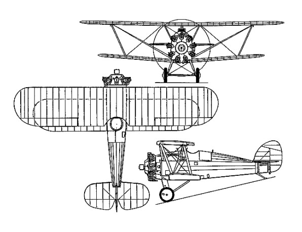
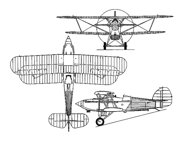
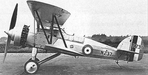
The Specification 21/26, issued by the Air Ministry’s Directorate of Technical. Development (DTD) on September 30, 1926, called for a “Single Seater Fighter Ship¬-plane for use from HM ships” fitted with a land undercarriage which could be replaced by floats, and vice versa, within half an hour. The aircraft, which was to have an all metal structure but could be fabric covered, was to be suitable for launch from a catapult and for taking off from and alighting on the deck of an aircraft carrier. It was to have a good degree of positive stability about all axes in both configurations, and tail incidence had to be adjustable in flight to enable the aircraft to fly horizontally at all speeds without attention from the pilot. It was to be “highly controllable” at all speeds, and especially close to stalling speed, with no tendency to ‘hunt’ in a steep dive. Control had to be adequate to stop an incipient spin when the machine was stalled. A high degree of manoeuvrability in the air and on the ground or water was desired, and it had to respond quickly to the controls while not being tiring to fly. The ailerons were to have the minimum of yawing effect. As a seaplane, the machine was to have good static stability in the water, and when under tow or running under its own power it was to be stable about all axes at all speeds. Engines specified were the air cooled Bristol Mercury radial giving 550hp at 2,000rpm or the water cooled Rolls Royce Falcon X giving 480hp at 2,300rpm. The installation had to allow for rapid and easy removal of the engine. The cowling, which also had to be easily removable, had to be finished “to prevent the reflection of light which might betray the presence of the aircraft to the enemy or dazzle the pilot”. A metal propeller was specified. There was to be tankage for 74 gallons of fuel, plus an easily removed 20 gallon auxiliary tank and a gravity tank of sufficient capacity to allow half an hour’s flight at full power at ground level. An 11 gallon oil tank was to be provided if the Mercury engine was used, or an 81/2 gallon oil tank and a 21/2 gallon reserve water tank for the Falcon. Alternative exhaust systems for day or night flying were required, and were to be easily changed. The night flying system had to provide adequate silencing and flame damping, while the daytime system was to be “of minimum weight”. Additional equipment to be carried during the acceptance flights weighed 5581b and included a Vickers 0.5in gun and 300 rounds, a Vickers 0.303in gun and 600 rounds, a rocket launching (R/L) tube and six bombs, and flotation gear. A second 0.303in gun with 600 rounds was to be provided for if the 0.5in gun was not available in time. Minimum performance requirements with this load, using the Mercury, called for a horizontal speed of 132kt (152mph) at 10,000ft and a service ceiling of 23,000ft. With the Falcon X the figures were 127kt (146mph) at 10,000ft and 22,000ft. The length of run to take¬off was not to exceed 47ft in a relative wind of 28kt (32mph), and the aircraft was to become airborne at a speed of 55mph when catapulted in still air. The suitability for launching from a catapult or alighting on the deck of an aircraft carrier was “of first importance”, and the aircraft had to be capable of taking off from a turret or cruiser platform. For fighting, the pilot was to have the best possible view in all directions, and a good view forward and downwards was required for carrier landings. A clear, unobstructed view forward over the machine’s centreline was needed to enable him to sight the fixed guns, the installation of which was to dispense with blast tubes. There was also to be provision for the fitting of a G.3 aerial camera as near to the sights as practicable, and standard clips were to be fitted to allow the new “light carrier” to be installed to carry four 20 lb bombs, sufficient clearance being provided to enable the bombs to be released in a very steep dive. Despite the emphasis placed on the machine’s naval use, it was stressed that: “The aircraft is to be designed primarily as a landplane fighter and qualities required for this work are not to be sacrificed in order to improve its characteristics when equipped with the float alighting gear”. A padded head support was to be provided to prevent injury to the pilot during catapult launch acceleration. A limit of 35ft was put on the wing span, the overall length was restricted to 23ft, the height was not to exceed 14ft 9in. Quick and easy removal and erection of the wings was specified, with the ability to remove the wing structure completely in ten minutes and replace it in fifteen minutes. The contractor was required to provide a full size mock up of his proposed aircraft before constructional work was begun, to enable the Director of Technical Development to examine and approve the layout. This mock up had to include “all parts and components which are likely to interfere with the all round view of the pilot”, and was to show the internal arrangement of the cockpit. Scale model floats for official water tank tests were also to be provided, along with specimens of ribs, a section of wing, and a length of spar. The Hoopoe, flown for the first time in 1928, was a two-bay staggered all-metal biplane powered by a 450hp Bristol Mercury II ninecylinder radial. Found to be seriously underpowered when first tested as a float fighter in 1929, the Hoopoe prototype was re-engined with a 520hp Mercury VI. Subsequently returned to the manufacturer after official handling trials at Felixstowe, the Hoopoe was fitted with a new single-bay wing cellule, a 400hp 14- cylinder two-row Armstrong Siddeley Jaguar V engine, and reverted to a wheel undercarriage for a further service assessment at Martlesham Heath. Various structural refinements were introduced and the Hoopoe was once again re-engined, this time with a 560hp Armstrong Siddeley Panther III. The prototype of the Nimrod fleet fighter had meanwhile commenced flight test, however, and thus interest in the Hoopoe had become no more than academic by mid-1930. None of the aircraft tendered to Specification 21/26 won a production contract.
Engine: 560hp Armstrong Siddeley Panther III Max take-off weight: 1761 kg / 3882 lb Empty weight: 1270 kg / 2800 lb Wingspan: 10.11 m / 33 ft 2 in Length: 7.47 m / 24 ft 6 in Wing area: 26.80 sq.m / 288.47 sq ft Max. speed: 315 km/h / 196 mph
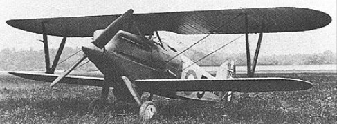
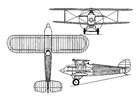
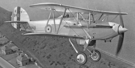
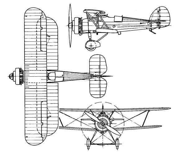
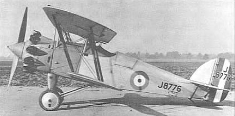
Designed by Sydney Camm as a potential successor to the RAF’s ageing Siskin fighter, the Hawfinch was built to Specification F.9/26, being one of nine contenders for RAF orders. Constructed in 1927 as a private venture, it was entered in the F9/26 competition at Martlesham Heath against the officially sponsored Annstrong Whitworth Starling, Boulton¬Paul Partridge, Gloster Goldfinch and Hawker Hawfinch. Flown for the the first time in March 1927, the Hawfinch was of fabric-skinned metal construction, with an armament of twin synchronised 7.7mm Vickers guns and powered by a supercharged nine-cylinder Bristol Jupiter VII radial of 450hp (which replaced a Jupiter VI shortly after the commencement of flight testing). Because of the closeness of the competition between the Bulldog and the Hawfinch the British Government ordered a single Bulldog II for further trials. The Bulldog II had a longer rear fuselage to overcome the spin deficiency of the prototype. First flown on January 21, 1928, the Bulldog II was tested against the Hawfinch at Martlesham, but the competition proved so close that a final decision was reserved until service pilots could assess both types. Eventually the decision was based on the ease of maintenance and here the Bulldog, with its single bay wings as against the twin bay wings of the Hawfinch, won. The Hawfinch prototype subsequently participated in various experimental programmes, during one of which the original two-bay wing cellules was replaced with single-bay cellules, other tests being conducted with a twin-float undercarriage.
Max take-off weight: 1320 kg / 2910 lb Empty weight: 873 kg / 1925 lb Wingspan: 10.21 m / 33 ft 6 in Length: 7.21 m / 23 ft 8 in Height: 2.84 m / 9 ft 4 in Wing area: 27.31 sq.m / 293.96 sq ft Max. speed: 275 km/h / 171 mph