Itoh Emi 13

From mid-1919 Otojiro Itoh’s flying school at Itoh Airfield at Tsudanuma had relied heavily on the Itoh Emi 9, its only two-seat trainer. Its designer, Tomotari Inagaki, had already designed a similar but improved successor, powered by the same Hall-Scott V-8 engine. This, the Emi 13, was built between the summer of 1919 and the following spring.

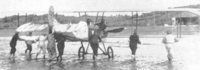
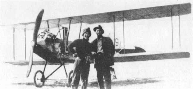
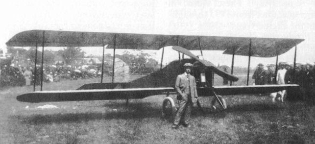
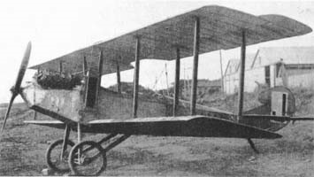
The Emi 13 was a wooden-framed, fabric covered two bay biplane with pairs of parallel interplane struts. Its wings were rectangular in plan, with overhung ailerons only on the upper wing. Tall, outward-leaning cabane struts braced the wing over the fuselage, where there was a broad trailing edge cut-out to increase the field of view from the rear seat. The lower wings were mounted on the lower fuselage longeron.

Its V-8 engine was nose-mounted with its upper parts exposed and a flat, narrow, rectangular radiator attached vertically just behind it on the port side where the engine cowling joined a flat-sided fuselage. The two separate cockpits of the Emi 5 were replaced by tandem seats in a single open cockpit, with the student under the central wing and the tutor under the trailing edge. This change was made to ease communication between them. Behind them the fuselage had rounded upper decking. The tail was conventional, with the horizontal surfaces mounted on top of the fuselage and the tailplane strut-braced from below. The fin was small and triangular in profile but carried a large rounded rudder with a prominent horn balance.

The Emi 13 had a single axle undercarriage with large wheels. The axle was rubber-sprung on a cross-braced frame with forward legs and trailing drag struts to the lower fuselage longerons. Its tall tailskid was mounted below the tailplane leading edge.

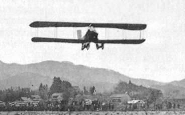
First flying c. May 1920, to demonstrate its abilities the Emi 13 took part in a competition sponsored by the Imperial Flying Association held In August 1920 in Tokyo. It gained the fourth prizes for both speed, at 109 km/h (68 mph; 59 kn) and altitude 1,370 m (4,490 ft).

By late 1920 the Hall-Scott engine was reaching the end of its life so Inagaki revised the design to take a 90 hp (67 kW) Curtiss OX-5, another water-cooled V-8. Itoh completed this aircraft, referred to as the Emi 13 no.2, in 1921 and it became the principal trainer at the flying school.

Engine: Hall-Scott V-8, 80 hp
Propeller: 2-bladed wooden
Wingspan: 10.37 m (34 ft 0 in)
Wing area: 29 m2 (310 sq ft)
Length: 6.40 m (21 ft 0 in)
Height: 2.50 m (8 ft 2 in)
Empty weight: 450 kg (992 lb)
Gross weight: 600 kg (1,323 lb)
Maximum speed: 106 km/h (66 mph, 57 kn)
Cruise speed: 95 km/h
Endurance: 2 hr
Time to1,000 m (3,300 ft): 7 min
Crew: one tutor
Capacity: one student

Itoh Emi 9

After the destruction of Itoh’s hangar at Inage Beach by a tidal wave at the end of September 1917 his works and flying school moved to Tsudanuma Beach, otherwise known as Itoh Airfield. The move led a significant increase in student numbers and a new, two seat trainer was needed; until then they had relied on single-seaters. The solution was provided not by Itoh or his employees but by a regular visitor to the airfield, Tomotari Inagaki. He designed a simple and stable two seat trainer around the water-cooled 80 hp (60 kW) Hall-Scott V-8 engine taken from the Emi 3. It became known as the Itoh Emi 9.

The Emi 9, typical of its time, had a wooden frame and fabric covering. It was a straightforward two bay biplane, with two parallel pairs of interplane struts on each side. The wings were rectangular in plan and manufacture was further simplified by the absence of dihedral or stagger.

Its upright V-8 engine was installed in the nose with most of the upper part exposed and its rectangular radiator mounted edge-on just behind the engine on the fuselage port side. Pupil and instructor had separate open cockpits in a fuselage rather similar to that of the Emi 5. Its tail was with a triangular fin, a rudder with a straight leading edge which continued that of the fin and a deep, rounded trailing edge, though the control surfaces had horn balances, the first to be used on a Japanese civil aircraft.

The Emi 9 had a simple, single axle undercarriage with legs on the lower fuselage longerons and trailing drag struts to the fuselage centre line.

Built in 1918 the Emi 9 served the Itoh school as intended, though details of its history are lacking.

Powerplant: 1 × Hall-Scott, 60 kW (80 hp)
Propeller: 2-bladed
Wingspan: 9.80 m (32 ft 2 in)
Length: 7.45 m (24 ft 5 in)
Height: 2.30 m (7 ft 7 in)
Empty weight: 350 kg (772 lb)
Maximum speed: 111 km/h (69 mph, 60 kn)
Crew: one instructor
Capacity: one student

Itoh Emi 3

Though by around 1916 demonstration flights by early Japanese aircraft were beginning to be commercially viable, there were no suitable seaplanes. Otojiiro Otoh, who had designed and built Japan’s second commercial landplane, the Itoh Emi 1, was encouraged to fill the gap. The result was the Emi 3, completed in August 1917.

Like most aircraft of its time, it was a wooden-framed and fabric covered biplane. It was a two-bay design with wings braced by two pairs of parallel, vertical interplane struts on each side but, as the upper wing had a significantly longer span, there was also pairs of parallel, outward- leaning struts to brace the overhang. Only the upper wings carried ailerons.

Its water-cooled 80 hp (60 kW) Hall-Scott V-8 engine drove a two-bladed propeller. Close behind it there was an open cockpit for one passenger; the pilot’s cockpit was just aft of the upper wing trailing edge. The Emi 3’s fuselage was flat-sided and quite slender, with the horizontal tail mounted on its top. Its fin had a triangular profile and carried a rudder of roughly parallelogram profile.

It had twin floats, mounted with a pair of single struts to the fuselage forward and a transverse W-form strut to the fuselage and lower wing aft.

The Emi 3 was built at Itoh’s Inage Beach site and, assisted by Toyokichi Daiguchi and Toyotaro Yamagata, and with the help of student pilots, the aeroplane was completed in August 1917. Flight tests by several pilots found its performance, stability and handling were good.

Test flights over, the Emi 3 was taken by rail to Osaka. In preparation for demonstration flights, the Emi 3 Seaplane was assembled and maintained in a hangar located on the beach at Nishinomiya, just west of Osaka. Spectators’ fees made these flights a commercial success for Japan’s first passenger-carrying floatplane. Itoh named the only example Seagull (Kamome, かもめ).

Powerplant: 1 × Hall-Scott water-cooled V8, 60 kW (80 hp)
Propeller: 2-bladed wooden
Upper wingspan: 15.41 m (50 ft 7 in)
Wing area: 46.5 sq m (501 sq ft)
Length: 7.27 m (23 ft 10 in)
Height: 4.51 m (14 ft 10 in)
Empty weight: 580 kg (1,279 lb)
Maximum speed: 43kt (50mph)
Crew: one
Capacity: one passenger

Itoh Emi 2

Itoh Emi 2

By early 1917 Itoh had begun the design of a new aircraft. The Emi 2 owed much to its predecessor, both biplanes with wooden structures and fabric covering. Rectangular plan wings, shorter in span by 2.50 m (8.2 ft) and using a lower drag profile than before, were braced with pairs of parallel interplane struts, though the Emi 2, a two-bay biplane, had one less bay on each side. The Emi 2’s upper wing had a slightly greater span than the lower one, which had more rounded tips. The centre of the upper wing was supported over the fuselage by four parallel cabane struts. As on the Emi 1 there were ailerons, with chords which increased outwards, only on the upper wings.

The Emi 2 also inherited its predecessor’s engine, the 26–34 kW (35–46 hp) Grégoire Gyp. The flat-side fuselage had an open cockpit for the pilot; a semi-circular cut-out in the upper trailing edge increased the pilot’s upward field of view. The long span horizontal tail was roughly rectangular in plan and mounted on the upper fuselage and the vertical tail also was also parallel-sided, though with a sloping top.

The Emi 2’s wide track landing gear had two, rather than four wheels, each on a landing leg with bungee cord shock absorbers.

It flew for the first time in April 1917.

From May 1917 Itoh gave a series of demonstration flights from his east Inage Beach base, culminating in a visit to his home town of Osaka in September. His timing was fortunate, as his Inage Beach hangar was flattened by a typhoon-related tidal wave at the end of the month, while t Emi 2he was away. Demonstration flights resumed until the Emi 2 began use as a trainer from Itoh’s new base at Tsudanuma Beach.

Its last operations were under new owners based near Hammamatsu. It was again used for demonstration flights, piloted by the inexperienced Asao Fikunaga aound Osaka from August 1919. One flight took him to his home town of Toyonaka but the Emi 2 overturned on landing and was badly damaged. It was rapidly repaired but in May 1920, leaving Osaka, the aircraft hit a house roof, ending its career.

Powerplant: 1 × Grégoire Gyp, 26–34 kW (35–45 hp)
Propeller: 2-bladed
Maximum speed: 85 km/h (53 mph, 46 kn)
Wingspan: 9 m (29 ft 6 in)
Wing area: 25 m2 (270 sq ft)
Height: 2.25 m (7 ft 5 in)
Empty weight: 250 kg (551 lb)
Crew: one

Itoh Emi 1

By early 1915 Otijiro Itoh had established the Itoh Aeroplane Research Studio and an associated flying school and by that autumn had completed his first design, the Emi 1. The “Emi” was a respectful nod to the district of Osaka where he grew up.

The sole Emi 1 was a three-bay biplane with a fabric covered wooden structure. Its wings were of equal span and joined by parallel pairs of interplane struts. The upper wing was well above the fuselage and the lower ones mounted on the lower fuselage longerons. The Hyabusa-go’s French, 35–45 hp (26–34 kW) Grégoire Gyp four cylinder, water-cooled inline engine powered it. Its pilot had an open cockpit. At a time when there were few prepared airstrips, landing gear needed to be robust and the Emi 1’s gear had two wheels on each leg.

Its first flight was on 11 November 1915.

On 8 January 1916, not long after the first flight, Itoh flew the Emi 1 from his base at Inage Bay to Tokyo. This took 55 minutes and was the first flight to Tokyo. He later flew it to 58 Japanese cities, partly to advertise his aircraft and partly to raise air-mindedness in Japan. The Emi 1 was the second successful Japanese aircraft, following the Narahara 4 ”Ohtori-go”.

Later the Emi 1 was re-engined at Inage Bay with a 50 hp (37 kW) Hino Type, remaining in use with the flying school.

Emi 1
Powerplant: 1 × Grégoire Gyp 26–34 kW (35–45 hp)
Propeller: 2-bladed fixed-pitch
Wingspan: 11.50 m (37 ft 9 in)
Wing area: 33 m2 (360 sq ft)
Length: 6.65 m (21 ft 10 in)
Height: 2.50 m (8 ft 2 in)
Empty weight: 350 kg (772 lb)
Maximum speed: 76 km/h (47 mph, 41 kn)
Crew: one

Isaacs Fury / PFA Isaac Fury

Fury II

Designed by John Isaacs, the Fury is a 7/10 scale, single seat wooden replica of the famous Hawker Fury biplane of the 1930’s. The Isaacs Fury Mk 1 prototype G-ASCM first flew in 1963 powered by a 65 hp Mikron III engine. In 1967 the prototype was modified to Mk 2 standard by installing a 125 hp Lycoming O-290 engine. This aircraft is stressed to 9g for aerobatics. Normal load limits are +5 and -1G.

Fury II

The fuselage is a spruce structure of rectangular cross-section, with a curved turtlede eking and plywood covered. The wing is made up of solid spruce, warren girder ribs, internal diagonal wooden bracing and fabric covering. Ailerons are on the top wing only. No flaps are fitted. N type cabane and interplane struts support the wings which have conventional external wire bracing. The airfoil section is RAF 28. The empennage is a wooden structure utilising solid spars, girder ribs and fabric covering. The tailplane is strut braced. The fixed landing gear incorporates rubber cord shock-absorption and 3.25 x 14” wheels. A 10 Imperial gallon fuel tank is located aft of the firewall. A luggage locker is provided behind the cockpit.

It is only offered as a scratch built project with plans from John Isaacs. It is also an approved type of aircraft by the PFA in the UK.

John Isaac had sold 200 sets of plans (revised in 1994) by 1998. The plans were then marketed by the Popular Flying Association.

Gallery

Engine: Lycoming
Wing span: 6.4 m
Wing area: 11.4 sq.m
MAUW: 454 kg
Empty weight: 333 kg
Fuel capacity: 68 lt
Max speed: 185 kph
Cruise speed: 160 kph
Minimum speed: 72 kph
Climb rate: 8 m/s
Seats: 1
Fuel consumption: 25 lt/hr
Plan price (1998): $120

Engine: Lycoming 0-290, 125 hp.
Span, upper wing: 2l ft 0 in.
Lower wing: 18 ft 2 in.
Length: 19 ft 3 in.
Wing Area: 123.8 sq.ft.
Wing Loading: 8.1 lb/sq.ft.
Fuel cap: 18 USG.
MAUW: 1000 lbs.
Weight Empty: 730 lb.
Stall Speed: 38 mph.
Cruise: 100 mph.
Vne: 135 mph.
Top speed: 115 mph
Range: 200 sm.
Take-off dist: 400 ft.
Vne: 160 mph.
ROC: 1600 fpm.
Ultimate Loading: +9/-4.5g.

Engine: Lycoming 0-235-C, 115 hp.
Range 160km (100 miles).
MTOW: 1000 lbs.
Empty wt: 675 lbs.
Wing span: 21 ft.
Stall: 30 kts.
ROC: 1400 fpm.
Load limits: +9 / -4.5G.

Engine: Lycoming 0-235 C2A, 125hp.
Prop: Henry 428 72in dia/44in pitch
Cruise 85kt @2400rpm
ROC: 1500fpm
Fuel burn @ cruise: 26 lt/hr
Load: +9/-5.