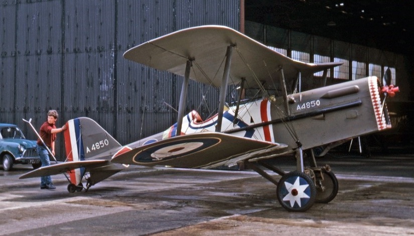
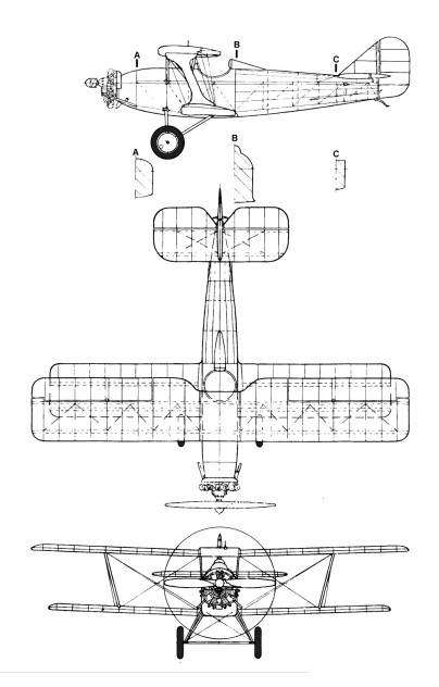
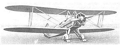
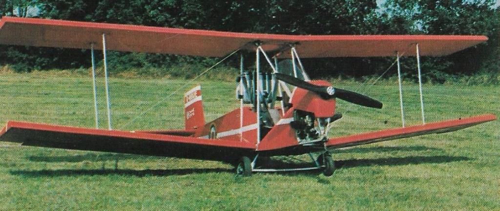
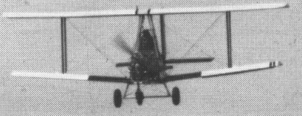
Single seat single engined biplane with con¬ventional three axis control. Wings have un¬swept leading and trailing edges, and constant chord; conventional tail. Pitch control by fully flying tail; yaw control by fully flying rudder; roll control by full span ailerons; control inputs through stick for pitch/roll and pedals for yaw. Wings braced by struts and dupli¬cated transverse X cables; wing profile; 100% double surface. Undercarriage has three wheels in tail dragger formation; coil spring suspension on tailwheel and axle flex suspension on main wheels. Push right go-¬right tailwheel steering connected to yaw control. No brakes. Composite fuselage, partially enclosed. Engine mounted between wings driving tractor propeller. Patented composite wing structure using waterproof fabric covering with heat set backing adhe¬sive. Rigging wires of stainless steel. Airframe uses aluminium alloy seamless drawn tube and cadmium plated aircraft quality nuts and bolts.
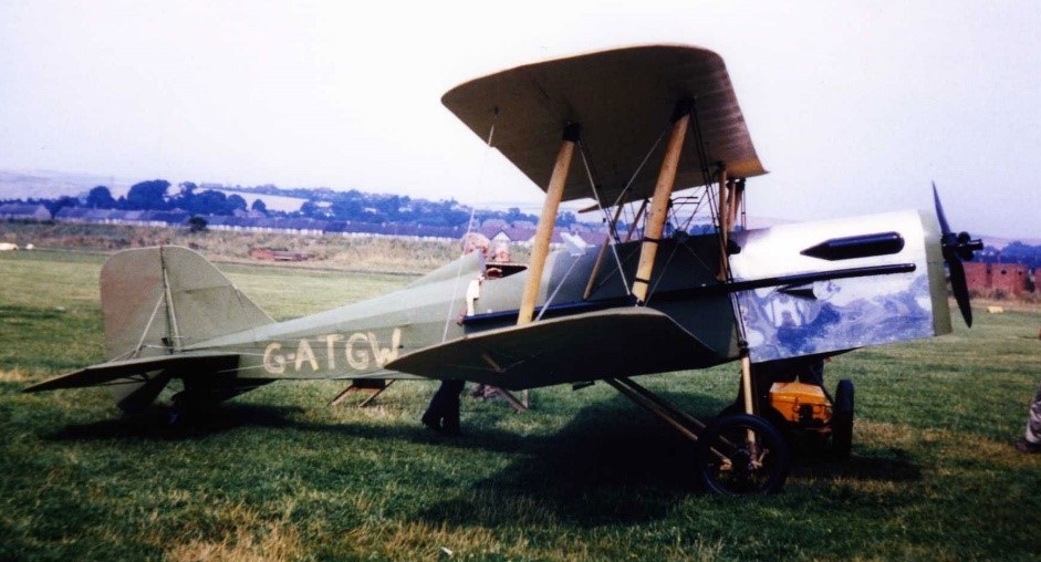
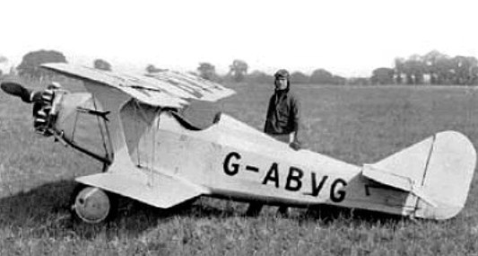
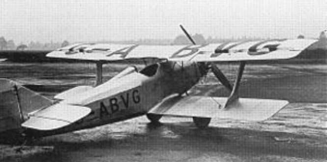
The Super Tiger Cub 440 is the logical development of the Micro Bipe prototype, with the open framework replaced by a partially enclosed cockpit and the 250 engine discarded in favour of a 440. Wing span is increased to keep the wing loading of this heavier aircraft within the UK microlight definition. Although a nosewheel was retained for test work on the pre production prototype of the Super Tiger Cub 440, it is not fitted on production machines. Particularly noteworthy is the ease of rigging. Simply by removing three locking pins per side, the Super Tiger Cub 440 is made ready for trailer transport.
The aircraft is offered in three forms: part kits, full kits or ready to fly. Part kits are numbered one to eight and can be purchased one at a time as the builder’s finance permits, a system which also permits the manufacturer to keep costs down by producing each part kit in quantity. By 1982 over 150 of these aircraft were in the process of being built.
Gallery
Engine: Robin EC44 50hp at 7000rpm
Propeller diameter and pitch 54 x 33 inch, 1.37x 0.84 m
Toothed belt reduction, ratio 2.4/1
Max static thrust 220 lb, 100kg
Power per unit area 2.72 hp/sq.ft, 29.7 hp/sq.m
Fuel capacity 6.0 US gal, 5.0 Imp gal, 22.7 litre
Length overall 13.3 ft, 4.05 m
Height overall 5.5 ft, 1.68m
Wing span 21.0ft, 6.40m
Constant chord 3.0 ft, 0.91 m (bottom wing), 3.5 ft, 1.07 m (top wing)
Dihedral 5 deg (bottom wing), 0 deg (top wing)
Sweepback 0 deg
Tailplane span 7.0ft, 2.13m
Rudder height 2.9ft, 0.88 m
Total wing area 136 sq.ft, 12.6 sq.m
Total aileron area 13.8 sq.ft, 1.28 sq.m
Rudder area 6.3 sq.ft, 0.59 sq.m
Total elevator area 14.6 sq.ft, 1.36 sq.m
Wing aspect ratio 6.4/1
Wheel track 4.2 ft, 1. 28 m
Tailwheel dia¬meter overall 4 inch, 10cm
Main wheels diameter overall 13 inch, 33cm
Empty weight 265 lb, 120kg
Max take off weight 500 lb, 227 kg
Payload 235 lb, 107 kg
Max wing loading 3.68 lb/sq.ft, 18.0 kg/m
Max power loading 10.0 lb/hp, 4.5kg/hp
Load factors +6.0, 4.0 design; +9.0, 7.0 ulti¬mate
Max level speed 80 mph, 129 kph
Never exceed speed 85 mph, 137 kph
Max cruising speed 70 mph, 113 kph
Economic cruising speed 60 mph, 97 kph
Stalling speed 30 mph, 48 kph
Max climb rate at sea level 900 ft/min, 4.6 m/s
Min sink rate 500 ft/min at 36 mph, 2.5 m/s at 58 kph
Best glide ratio with power off 7/1 at 35 mph, 56 kph
Take off distance 60 ft, 20 m on short grass
Landing distance 80 ft, 25 m on short grass
Service ceiling 10,000 ft, 3050 m
Range at average cruising speed 115 mile, 185 km