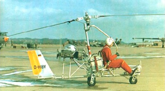
In 1968, VFW (Vereingte Flugtechnische Werke) built an experimental open gyrocopter modelled on the Bensen B.8M. This VFW-H2 was unusual in having ducted rotor blade tip jets supplied from the 72hp McCulloch engine. The engine itself was mounted behind the pilot and drove a two-blade pusher propeller.
The H-2 (D-HIBY) was followed by a more sophisticated machine – the H-3 Sprinter which had a completely enclosed fuselage structure with a three-seat cabin, slim low-set tailboom with a V-tail, and a tricycle undercarriage.
The VAK concept of NATO and the German Armed Forces required an aircraft that was able to take off from unprepared airfields without runways. Its mission was close air support. In addition it had to be able to fly long distances in extreme-low-altitude in order to prevent attacks of antiaircraft weapons and radar detection. Because of this the VAK was designed with short wings and a minor extension so it would provide its pilots a tolerable flight and bear aerodynamically difficult extreme low altitude flights.
The first prototype flew on September 10, 1971, powered by one 10,150-lb (4604-kg) thrust Rolls-Royce/MTU RB.193 vectored-thrust turbojet and two 5577-lb (2530-kg) thrust RB.162 lift turbojets. It had small, vertically mounted jets in the front and rear of the fuselage for direct lift, plus a third engine of the vectored ¬thrust type for forward propulsion and transitions between horizontal and vertical flight. It uses “puffer jets” at the nose, tail and wingtips to stabilise it during low speed and hovering man¬oeuvres. In terms of design, it is intended for experimental work only. The first transition – the transfer of vertical flight in horizontal and vice versa as well as turning off and on the lift-engines – was achieved on October 26, 1972 in Manching, Bavaria, at a speed of 400 km/h. All three VAK 191B experimental aircraft completed a total of 91 flights that lasted all together 12 hours.
Despite successful flight trials it was not ordered into production as the Harriers of RAF Germany were already fulfilling the need for which the VAK-191B had been conceived.
VAK 191B Engines: 1 x Rolls-Royce/MTU RB 193-12, 45.2kN + 2 x Rolls-Royce RB 162-81 F 08, 26.5kN Max take-off weight: 8507 kg / 18755 lb Empty weight: 5562 kg / 12262 lb Wingspan: 6.16 m / 20 ft 3 in Length: 14.72 m / 48 ft 4 in Height: 4.30 m / 14 ft 1 in Wing area: 12.5 sq.m / 134.55 sq ft Max. speed: 1100 km/h / 684 mph Cruise speed: 740 km/h / 460 mph Range: 400 km / 249 miles Payload: 2945kg Crew: 1
Germany Established late 1963 as Vereinigte Flugtechnische Werke GmbH (VFW), from merger of Focke-Wulf GmbH and Weser Flugzeugbau GmbH, joined in 1964 by Ernst Heinkel Flugzeugbau. During 1968-1969, acquired 65% holding in Rhein-Flugzeugbau GmbH, later becoming 100% owner of RFB. Henschel joined VFW in 1969. From 1 January 1969 became joint partner with Fokker of the Netherlands, mainly for marketing purposes, renamed VFW-Fokker GmbH, partnership lasting until 1980. Programmes in late 1960s/early 1970s included VAK-191B V/STOL and VJ 101 tilt-engine research prototypes, H2 (autogyro) and H3 (compound helicopter) experimental rotorcraft. VFW was involved in major licence production of Lockheed F-104G Starfighters (with Fokker), Sikorsky CH-53Gs (with Dornier and MBB) and Bell UH- 1D helicopters, and was overall programme manager for Transall C-160 heavy military transport (built with Nord/Aerospatiale and HFB/MBB). Was involved in design/construction of Dornier Do 31E VTOL transport; built major components for Fokker Fellowship, Airbus A300B and Panavia Tornado; was major overhaul facility for several important military and civil aircraft; also member of European Spacelab consortium. Principal late aircraft programme was VFW 614 twin-turbofan shorthaul transport (first flown July 1971), but production of this halted 1978. Taken over by MBB 1981.
This Spanish “Multiplano”, with seven wings and four horizontal control surfaces, was designed by Francisco Verdaguer and built in 1909 at the “A.L.A.” (Association de Locomocion Aeria) of Barcelona.
A two seat fully enclosed autogyro. Side by side seating. Composite body, airframe of square T-6 aluminium tubing, V tail. Engine: Rotax 582 or 618. Prop: 72” IvoProp carbon fibre, ground adjustable. Rotor blades: 27’ Dragon Wings.
Revealed in June 1987, the Venga TG-10 is a privately financed composite-construction, single engined jet trainer/light attack aircraft with tandem seating. Funding difficulties slowed the programme significantly in late 1987. The first flight has consequently been rescheduled several times, and had not taken place by July 1989.
In September 1988 Venga announced a joint-venture agreement with a Malaysian partner who were to produce the TG-10 in Sabah State, East Malaysia. Royal Malaysian Air Force interest was claimed, although no orders had been placed by July 1989.
An all-composites airframe and modular construction are intended to give the TG-10 an estimated flying life of about 10000 hours, due to a considerable reduction in the corrosion and fatigue problems associated with aircraft of metal construction. Its configuration also incorporates low-observables design features intended to improve its survivability. It will be repairable in the field, using replacement major components and quick-change engine modules, and will be operable from roads, grass or unprepared airstrips, with mission capability not only for its primary role as an `all-through’ trainer but also, in single-seat form (with the rear cockpit module removed), as a light ground attack aircraft.
AIRFRAME: Construction utilises a modular, all-composites structure designed for ease of repair in the field, built from pressure formed foam core laminates bonded together into a single lightweight moulded unit. Materials used are layers of aircraft grade glassfibre cloth bonded to a core of PVC foam (Klegecel or Divinycell) in a vacuum process using various resin matrices. Primary structure built entirely of composites materials, with extensive use of carbonfibre for high stress and other critical areas, though use of carbonfibre reinforced aluminium alloy (eg for main spars) is a customer option.
WINGS: Cantilever low-wing monoplane, with 2o 30′ dihedral from roots. Trailing-edge flaps are operated electrically via Commercial Aircraft Products actuators. Differentially operating ailerons, each with trim tab.
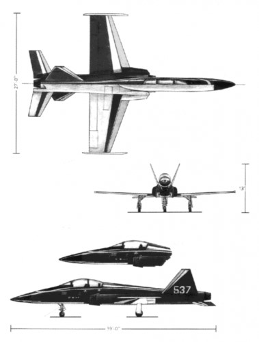
FUSELAGE: Modular structure (see `Airframe’ paragraph), of similar general appearance to Northrop F-5E. Electro-hydraulically actuated airbrake beneath fuselage.
TAIL UNIT: Low-set, sweptback tailplane with slight anhedral. Twin non-swept, outward canted fins, with inset rudders, forward of horizontal surfaces. Trim tabs in elevator and each rudder.
LANDING GEAR: Retractable tricycle type, with electro-hydraulic actuation; nosewheel retracts forward, mainwheels inward into fuselage. Wheel sizes 5.00-5 (nose), 6.00-10 (main). Nosewheel steerable through 30o. Mainwheels have hydraulic brakes and parking brake.
POWER PLANT: Prototype powered by one 13.01 kN (2925 lb st) General Electric J85-GE-5 turbojet; standard engine for basic production version will be an 11.12 kN (2500 lb st) Pratt & Whitney Canada JT15D-4C turbofan, but customer options will include General Electric CJ610 or Rolls-Royce Viper 632 or 680 turbojets. Intakes are each fitted with a large splitter plate, and are designed to inhibit foreign object damage. Fuel system, designed to permit fully aerobatic manoeuvres, comprises three fuselage cells with total usable capacity of 1223 litres (323 US gallons; 269 Imp gallons). A 265 litre (70 US gallon; 58 Imp gallon) drop tank can be carried on the fuselage centreline station in the single-seat attack configuration.
ACCOMMODATION: Standard trainer has tandem accommodation for pupil (in front) and instructor on UPC zero/zero ejection seats under jettisonable bubble canopy, with internal screen between cockpits. Seats are reclined, adjustable horizontally and vertically, and can accommodate back-type parachutes. Dual controls standard, except for switches for fuel pumps, weapon control panel and parking brake; in lieu of these, rear panel has a full set of indicators for the weapons system, an override switch to prevent firing, and a parking brake indicator. Rail mounted rear seat and rear instrument panel module are easily removable to permit quick conversion to single-seat light attack configuration. Cockpit(s) fully air-conditioned, but not pressurised; latter may be offered later as a customer option.
SYSTEM: 28V DC electrical system, powered by a standard starter/generator and Gates Energy Products lead-acid battery, with second battery for emergency backup. Power sources are coupled to three busbars in front cockpit (main, avionics, and emergency) containing trip-free circuit breakers. NATO type external ground power socket. Normalair-Garrett diluter demand oxygen system, capacity 225 litres (8 cu ft).
AVIONICS AND EQUIPMENT: Avionics include two VHF com, intercom, VOR/ILS/marker beacon receiver (front), VOR/LOC nav (rear), ADF, transponder, and DME. Full IFR capability, with electrically driven gyro instruments; main directional gyro is a King slaved type unit. Provision for HUD, radar altimeter, nose radar or other avionics to customer’s requirements. Standard cockpit instrumentation and equipment includes ASI (two), VSI (two), encoding altimeter, standard altimeter, clock (two), horizon gyro (two), turn and slip indicator (two), accelerometer (two), angle of attack indicator, pictorial navigation indicator, magnetic compass (two), DME indicator (two), ADF information display (two), first aid kit, IFF transponder, fire extinguishing system, and internal/external lighting.
ARMAMENT: One centreline and four underwing hardpoints, each stressed for loads of up to 181.5 kg (400 lb), for weapons, fuel tank (centreline only), survival or rescue packs, or other stores, subject to a max external load of 845 kg (1864 lb) in single-seat attack version. Weapons specified at present include up to three Portsmouth Aviation 7.62 mm FN gun pods with 450 rds/gun; up to three HMP 0.50 in Browning gun pods with 250 rds/gun; two GIAT 20 mm M621 gun pods with 150 rds/gun; various rocket launchers (Matra F2 with six 68 mm, Aerea AL 18-50 with eighteen 2 in, AL 8-70 with eight 2.75 in FFAR, AL 6-80 with six 81 mm, LAU-32 with seven 2.75 in FFAR, SNIA 2 in, Brandt 7 with seven 68 mm, or SURA-D 81 mm); SAMP 32 kg or 50 kg general purpose or 120 kg fragmentation bombs; 11 kg Mk 76 practice bombs; or a 70 mm automatic panoramic IRLS reconnaissance pod.
Venga reports that it has received letters of interest from five countries, involving approximately 160 aircraft. Rollout of the TG-10 prototype was anticipated in the Summer of 1989, subject to funding availability, and recent joint venture arrangements are claimed to have ensured funding to completion at about that time.
The first prototype was to be assembled in Montreal, but the US Thunder group was responsible for the engineering design of the TG-19, and the moulds were manufactured at Scottsdale, Arizona.
Venga was a struggling company throughout the ’90s. When the Venga TG-10 prototype was burned, it had a drastic impact on them. This was their major project that had been presented to the world. There was a decent degree of interest, and they had even formed a partnership. All of this changed on that day in May of 1998.
Without an actual prototype, there was no reason for anyone to have even the slightest interest. This is especially true given the fact that there were many other aircraft available now for a comparable price.
Venga TG-10 Wing span: 8.23 m (27 ft 0 in) Wing area: 12.54 sq.m (135.0 sq ft) Wing chord at root: 2.29 m (7 ft 6 in) Wing aspect ratio: 5.4 Length overall: 11.89 m (39 ft 0 in) Fuselage Max width: 1.42 m (4 ft 8 in) Height overall: 4.04 m (13 ft 3 in) Tailplane span: 3.96 m (13 ft 0 in) Wheel track: 3.05 m (10 ft 0 in) Trailing-edge flaps (total): 1.30 sq.m (14.0 sq ft) Rudders (total, incl tabs): 1.11 sq.m (12.0 sq ft) Tailplane: 1.67 sq.m (18.0 sq ft) Elevators (total, incl tab): 1.67 sq.m (18.0 sq ft) (A: two-seat trainer, B: single-seat attack): Weight empty, equipped (incl unusable fuel): A: 1288 kg (2840 lb) B: 1047 kg (2308 lb) Max usable internal fuel: A, B: 908 kg (2002 lb) Max external stores load: A: 277 kg (610 lb) B: 845 kg (1864 lb) Max T-O weight: A: 2645 kg (5832 lb) B (without external stores): 2041 kg (4500 lb) B (with max external stores): 2886 kg (6364 lb) Performance: (estimated: prototype with J85 engine at 2645 kg; 5832 lb max T-O weight): Max level speed: at S/L, ISA: 485 knots (899 km/h; 558 mph) at 9150 m (30000 ft), ISA: 450 knots (834 km/h; 518 mph) Stalling speed: 78 knots (145 km/h; 90 mph) Max rate of climb at S/L, ISA: 2134 m (7000 ft)/min Time to 9150 m (30000 ft): 7 min 12 s T-O run at S/L, ISA: 186 m (610 ft) T-O to 15 m (50 ft) at S/L, ISA: 402 m (1320 ft) Ground turning radius, all wheels rolling: 6.10 m (20 ft 0 in) Max range: internal fuel only, 10% reserves: 950 nm (1760 km; 1094 miles) with c/l drop tank, no reserves: 1271 nm (2355 km; 1463 miles) Max endurance at 9150 m (30000 ft): 2 h 30 min
Canada Signed agreement in 1994 with Baoshan Iron & Steel Complex in China to develop Timberwolf turboprop-powered sporting aircraft plus a jet trainer based on the Venga TG- 10 Bushfire.
In 1910 Raoul Vendome built a monoplane weighing 100 lb. The folding aeroplane incorporated several features. It could be assembled or dismantled by two people in four minutes. When folded it could be stored in a space of 7 x 10 x 17 feet.
Vendome tried to perfect a simple, cheap aeroplane that anyone could build at home.