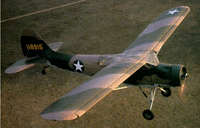
The 1940 L-1 Vigilant liaison aircraft is the military variant of the Stinson model V-74. The prototype L-1 with full-span automatic slots and slotted flaps for Army evaluation first flew on 15 July 1940, piloted by Al Schramm. It operated in and out of a 200′ circle.
Originally designated the O-49, redesignated from O-49 to L-1 in April 1942, with early ones briefly designated L-49, the 334 O-49s were designated L-1C for the air ambulance role, L-1D as trainers in glider pick-up techniques, and the L-1E and L-1F air ambulances with floats. Designations for those in ambulance duties were appended with suffix -VW.
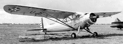
First flying on 15 July 1940, piloted by Al Schramm, priced at $21,000, one hundred and forty-two were built; 40-192 to 40-291, and 40-3101 to 40-3142, of which 14 went to the RAF as Vigilant IA.
One hundred and eighty-two L-1A / O-49A were built; 41-18900/19081, plus 54 to the RAF as Vigilant I.
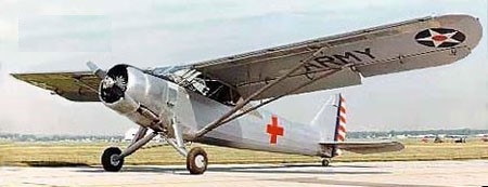
Four L-1A were converted to L-1B / O-49B Ambulance version in 1942.
The L-1C of 1942 were L-1A 113 converted as ambulances
Twenty-one L-1A were converted to glider tug trainers as L-1D.
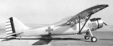
The 1943 L-1E were seven L-1 converted to amphibious ambulance, equipped with twin-EDO floats.
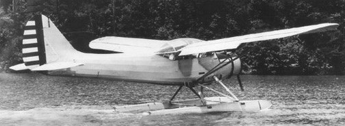
The L-1F of 1943 is similar to L-1E with minor modifications. Four conversions from L-1A and 1 from L-1C were made, plus a few converted to CQ-2 target controllers.
The L-1T was a glider tug conversion of L-1.
105 L-1s were received by the RAF as the Vigilant I.
A few L-1F were used as aerial target controller late in the war, designated CQ-2.
Professor E A Stalker conducted numerous wind tunnel and aeroplane design studies in the late 1930s and in 1942 was given a $50,000 contract by the USAAF to modify Stinson-Vultee L-1 40-255 with a suction flap arrangement. The contract was actually to the Dow Chemical Co of Bay City MI, where Stalker was employed.
Modifications consisted essentially of a new plywood wing that contained full-span, double-segment flaps together with full-span suction slots and ducts, plus addition of a suction blower in the fuselage driven by an auxiliary 80hp Franklin O-180-1.
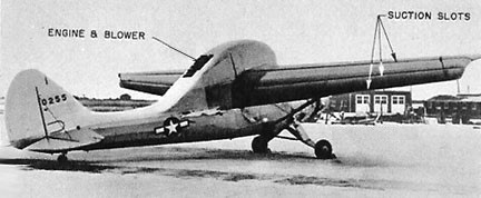
The two-section flap covered 40 percent of the chord—the front section deflecting to 35 degrees and the rear to 82 degrees in the fully down position. The outboard section of the aft flap had an additional independent travel of 22 degrees and 33 degrees in the flap’s down and up positions, respectively, which provided lateral control. A large hump in the fuselage housed the blower, and louvres on the rear of the hump controlled the pump’s exit flow.
Its first flight was made on 6 Mar 1944 at Tri-City Airport (p: Maj R E Horner), followed by 19 flights by Dow test pilot R B Gorrill. After a limited amount of testing by Stalker’s group, the L-1 was transferred to Wright Field for additional tests. During early stall tests it entered an uncontrollable spin and crashed, killing pilot Lt P A Hobe.
This first effort was something of a state-of-the-art experiment. The mechanism for boundary layer control was bulky and complicated and, although it worked satisfactorily (a maximum lift coefficient of 3.6 was obtained), the benefit to aircraft performance was difficult to measure—indeed, the gain was practically cancelled by the increased weight of the special wing, engine, and ducting.
Besides, the L-1 was perhaps an unfortunate choice for this experiment since the standard model itself had slotted leading edges, flaps, and an unusually large wing area, all of which made it a high-lift aircraft in its original configuration. When Stalker on 20 Jan 1945 reviewed the L-1 programme, he noted that ‘mechanical, structural, and weight difficulties have thus far prevented successful application to military or commercial airplanes,’ despite the general acceptance of laboratory and theoretical demonstrations of boundary layer control. He felt that the major drawbacks made evident by the L-1 modifications were very poor lateral control and restrictive weights of wing and blower. He also forecast future problems from lack of internal wing space for fuel, guns, or wheels, as well as structural difficulties in adapting boundary layer control to thin wings.
L-1 / O-49
Engine: 295hp Lycoming R-680
Wingspan: 50’11”
Length: 34’3″
Useful load: 732 lb
Max speed: 122 mph
Cruise: 109 mph
Stall: 44 mph
Range: 280 mi
Ceiling: 18,000′
L-1A / O-49
Engine : Lycoming R-680, 295 hp
Length : 36.844 ft / 11.23 m
Height : 10.531 ft / 3.21 m
Wingspan : 54.724 ft / 16.68 m
Max take off weight : 3384.7 lb / 1535.0 kg
Max. speed : 106 kts / 196 km/h
Cruising speed : 94 kts / 175 km/h
Service ceiling : 19373 ft / 5905 m
Range : 244 nm / 451 km
