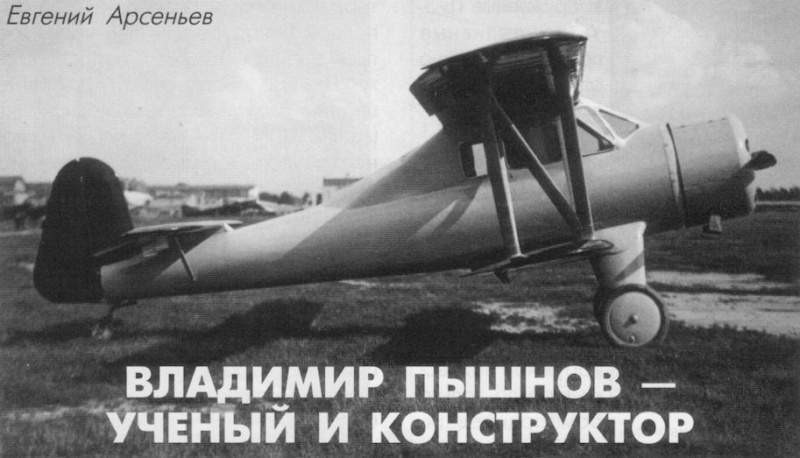
In addition to scientific-investigative work, VS Pyshnov once again decided to try its hand at construction activity. In 1935 he developed the project of a light aircraft that received the name VVA-1 (Military Aeronautical Academy – 1).
The VVA-1 was designed to meet the requirements of a light aircraft contest promoted by Osoaviajim in 1934. During the design, Pyshnov placed special emphasis on obtaining comfort for the passengers, the exterior finish of the model and the decrease in landing speed, obtaining a multi-purpose aircraft intended for use as a trainer, tourism aircraft, light transport and liaison aircraft.
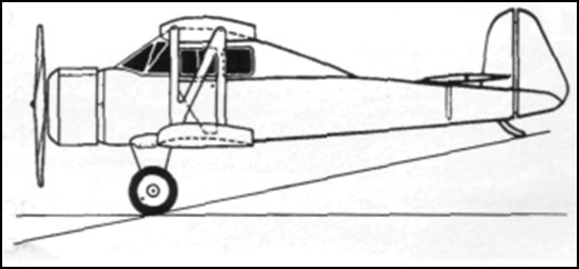
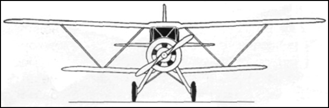
Structurally, the VVA-1 was designed as a sersquiplane with wings of equal width and a closed cabin made almost entirely of wood, using pine for the structure and plywood for the fuselage covering. The cowl was covered with steel plates and the wing and control surfaces were covered with fabric.
The fuselage featured a monocoque structure with a circular cross section. The construction had 17 frames and 4 stringers of variable section (30 x0 30 mm in the engine area and 20 x 20 mm in the tail area, as well as 10 stringers of 10 x 15 mm. The fuselage had a plywood covering of 3 mm in the front and tail area and 2 mm in the central area. To ensure greater rigidity, the fuselage had practically no perforations.
The wing box had a wooden structure with rigid “W” braces. The wing was rectangular in shape with rounded wingtips and consisted of two box-frame spars with three layers of pine and 3mm plywood walls. The leading edge was produced independently, being mounted on the wing once the fabric covering was finished. The wing struts were also made of pine with an aerodynamic profile and their junction with the wing was faired to reduce drag. Ailerons were included only on the upper wing, which also featured flaps that could be operated up to 30º angles. Norton-Shrenk type flaps capable of tilting at 45º were included in the lower wing.
The wing profile of the midline responded to that of the TsAGI-RP profile with decreased curvature, but the thickness responded to the NACA profile with a relative thickness of 10.5%.
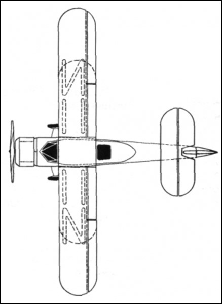
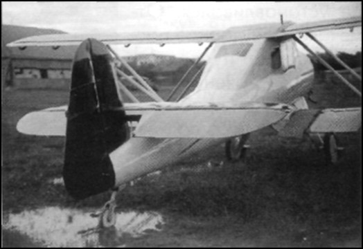
The upper wing consoles were fixed to the centerplane located above the closed cockpit. The lower wing was fixed directly to the fuselage and to reduce interference in the joint area it presented an inverted gull configuration. Another notable feature was the possibility of collecting the wings backwards, pivoting on the rear spar. In this way the width of the aircraft decreased from 11 to 3.4 meters.
The tail section featured an unconventional design. The horizontal stabilizer was located quite forward on the tail cone and on top of the fuselage. The empennage was cantilever and was fixed to the last frames of the fuselage. This configuration was specially selected in order to improve the work of the tail unit in the event of a spin entry, by eliminating the influence of one surface on the other.
The stabilizer had a main spar located over 27% of the wing chord and a secondary spar located on the elevator attachment edge. The uprights that were attached to the structure on both sides of the fuselage were attached to the main spar. The front of the stabilizer was lined with plywood. The rest was received with tissue. The angle of incidence of the stabilizer could be adjusted on the ground. The structure of the depth rudder was made of wood with a textile covering.
The VVA-1 featured duplicate sticks, but the second stick could be removed. The double control pedals were linked to each other by means of a tube. Elevator control was mixed. In the lower part of the cabin it was rigid, but further on it was still on cables. Control of the ailerons was rigid, while that of the elevator was cable. The aileron actuators could be easily disengaged to allow retraction of the wings.
The main landers featured aerodynamically faired legs and rubber shock absorbers with 700 x 100 mm unbraked wheels. The tail unit also featured spring damping and was free to rotate. The rear landing gear was calculated to install a skid or a wheel, interchangeably.
The powerplant selected was the 110-hp air-cooled M-11 radial engine. The engine was fixed to the fuselage by four points with the help of a frame made of “M” steel. The engine was covered by two hoods, one inside and one outside. To ensure engine cooling, the outer hood had adjustable holes located in front of the cylinders. The flight could be carried out only with the inner hood. For the VVA-1 a special fixed-pitch wooden propeller was designed.
The engine’s power system consisted of two fuel tanks. The main tank had a capacity of 100 liters and was located in the center of the plane. About the cabin. The second tank was located in the fuselage, between the engine and the cockpit instrument panel. The motor feeding could be done from each tank independently or from both. In the upper tank, a floating system was located that indicated the remaining fuel. The lubrication system was taken from the Polikarpov Po-2.
The cabin of the VVA-1 was closed and in the normal version it accommodated three people. The plioto was located in the front left position and behind it was a divan for two passengers. On the pilot’s right side a fourth seat could be installed to use the aircraft’s dual control system. To access the cabin, two doors located on the sides, on the lower wing, were used.
The instrument panel included a speedometer, turn signal and artificial horizon, barometer, clock, compass, rev counter, engine temperature and oil pressure indicator. Lighting was installed for the panel and for the cockpit.
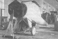
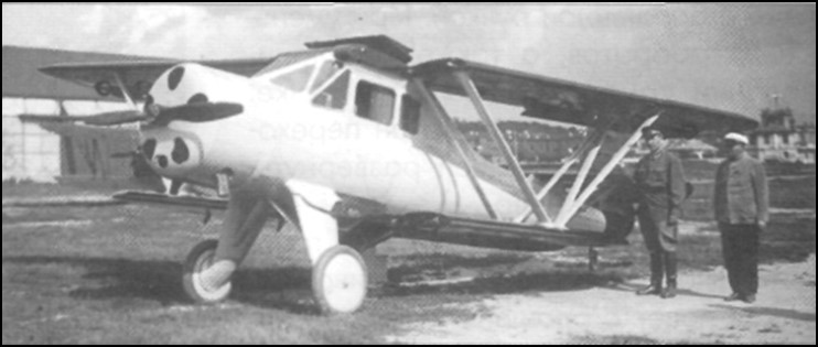
The VVA-1 was built in the workshops of the Military Aeronautical Academy. In the summer of 1935 the plane was ready for testing. In relation to the calculations of the project, the plane turned out to be much heavier. Calculated for an empty weight of 580 – 600 kg the prototype weighed 845 kg, with a takeoff weight of 1146 kg.
In August 1935 the aircraft was handed over to the NII VVS for development of state tests. NS Kulikov was designated as the main engineer and the test pilot was KA Kaliliets. The test program established 14 flights to establish the benefits and the main operating data. The tests took place between August and September and were carried out without the outer bonnet and without the planned propeller. When testing this propeller, both on the ground and in flight, a large vibration appeared throughout the airframe. For this reason this propeller was replaced by that of a Po-2. With this propeller the vibration did not completely disappear, but it decreased considerably. In the tests, a speed of 156 km/h at sea level was obtained with a takeoff weight of 1146 kg and 145 km/h at 2000 meters of altitude. The height of 1000 meters hated to be reached in 9.83 min and the 2000 m in 26.19 minutes. The ceiling of 2920 meters could be reached in 76.9 minutes. Landing speed with flaps extended was 75 – 90 km/h.
The plane behaved well on takeoff, but it was heavy and the tail lifted with difficulty. It lacked a tendency to take off from the ground, so the pilot felt the need to “force” it. Using the flaps did not improve takeoff, shortening it only by about 60 meters. Another problem was the tendency of the plane to drift during the takeoff run, which forced the pilot to not neglect control of the controls to correct the problem.
The rate of climb was considered very low. To rise to 30 meters, the plane needed to travel 500 or 600 meters, which, together with a run of about 240-300 meters for takeoff, made it impossible to use it at aerodromes with short runways or with obstructions near the end of the runway.
Visibility from the cabin forward and to the left was considered good, to the right and to the sides, bad and to the rear was not possible. Long flights were exhausting for the crew, especially due to the poor distribution of the steering components and the uncomfortable position of the seats.
In calm skies the plane behaved quite well, but in turbulence its behavior was capricious. Maintaining the instrument course was quite difficult as the compass was far away on the panel and it was difficult for the pilot to follow it.
Unlike takeoff, landing was very easy. The aircraft landed with good stability. Without the flaps the landing run increased to about 180 meters.
In the report it was stated that due to the discomfort of the seat, the poor distribution of the instruments and equipment, the excessive sensitivity of the rudder, the low ascent speed and the lousy design of the control organs, the VVA-1 demanded too much attention of the pilot. As positive values of highlighted the excellent stability and ease of handling.
The military pilots pointed out that the performance obtained was too low and the aircraft too heavy, which led to a considerable decrease in the calculated payload capacity. The takeoff and landing runs were too long and the takeoff technique too complex, which confined it to operation on large aerodromes with good runways. The use of the flaps was very ineffective and the landing speed remained high. The poor work of the flap control organs, the uncomfortable position of the control stick, the poor vision through the cockpit glass in bad weather and the absence of rearward and upward visibility were also noted.
In the conclusions of the report it was written: ” due to its performance and operating data, the VVA-1 aircraft is of no interest… “
It was considered useless to make modifications to the plane because it was considered that the main drawbacks of the plane came from its aerodynamic design, but the possibility of building a new example that took advantage of the positive elements of the design was left open, while at the same time managing to eliminate the indicated deficiencies and cover the requested technical specifications. Budget cuts at the Military Aeronautical Academy prevented the construction of this new model.
Given the impossibility of building a new prototype, the first VVA-1 was modified in order to reduce some of the signals made during the tests. Among the changes made, work was done to improve the control of the rudder by reducing its surface and installing a compensation system to reduce sensitivity. The landing gear was modified, a more powerful powerplant was installed and the hood was modified. Added a new fuel tank. The fairings at the junctions between the W-pillars and the wing were removed. These changes increased the empty weight of the plane to 1,160 kg, so military use was ruled out, defining the use of the model as a sports and tourism plane.
In 1937 the modernized VVA-1 was delivered to the NII VVS and several familiarization flights were carried out on it. These flights demonstrated stability problems in the vertical axis. The builder was asked to increase the surface of the empennage and replace the wheel train with one made of skis. Lack of funds for development programs at the Military Aeronautical Academy prevented further modifications.
VVA-1
Powerplant: One 110 hp M-11
Wingspan: 11.0 m
Wing area: 21.28 m²
Length: 7.8m
Height: 2.85m
Empty weight: 845 kg
Maximum takeoff weight: 1146 kg
Fuel capacity: 110 kg
Payload: 301 kg or 2 passengers
Maximum speed: 156 km/h
Minimum flight speed: 100 km/h
Landing speed: 75-90 km/h
Cruising speed: 135 km/h
ROC: 2.05 m/s
Ceiling: 2920 m
Take-off run with flaps: 220-260 m
Landing roll: 180-200 m
Accommodation: 1 – 2