Back to Dickson Primary
Mr. R. S. Dickson writes:
When the clubs start flying, the most popular glider will be the cheap training type, the high performance machine only being suited to experts who will probably own their own pet machines. In any case every person must start on a training type; even the best of pilots are not used to the light loading common to all gliders, and would have a little trouble at first. In view of these facts it is proposed to attempt to standardise the simple glider, and to this end the machine shown in the accompanying drawings has been designed.
The construction throughout is extremely simple, and the average amateur should have no difficulty in completing the machine. This glider has been designed with high factors throughout, and is very robust. The estimated weight without pilot is 180 lbs., thus giving a wing loading of approximately 2 lbs. per sq. ft. with an average pilot. The landing speed is 22 m.p.h., so that in an ordinary light breeze the relative ground speed will only be about 7 m.p.h. The wing section used, the C Y.H., has a high maximum lift, low drag, and a fairly stable centre of pressure. External wire bracing is cheaper and simpler to repair than a pure cantilever wing, and there are no bracing wires inside the air surfaces, their place being taken by spruce strips.
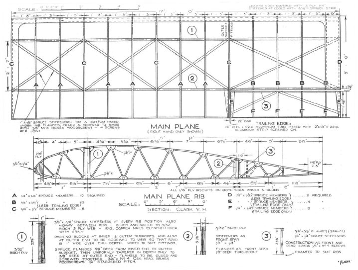
Wing construction of the ” Dickson ” glider
The general scheme has been to use just a few standard sections of spruce, and thereby make the glider simple and inexpensive. This method does not, of course, allow the use of the most economical design, but the advantages gained for the purpose for which the glider is intended, far outweigh the disadvantages.
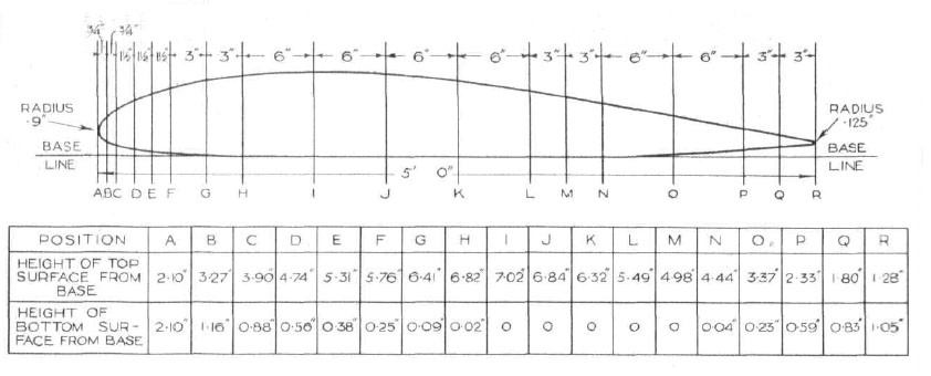
Ordinates of the C.Y.H. aerofoil section laid, out on a 5-ft. chord, so that those who are constructing the Dickson Glider. The factors which have been adhered to in the design of this glider are actually somewhat higher than those suggested by the Gliding Association, so constructors need have no fear on the score of strength. A somewhat piquant situation is now possible as the R.A.E. state that there are no official requirements for gliders and no C. of A. (Certificate of Airworthiness) is required.
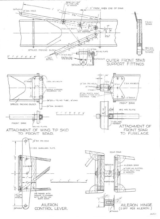
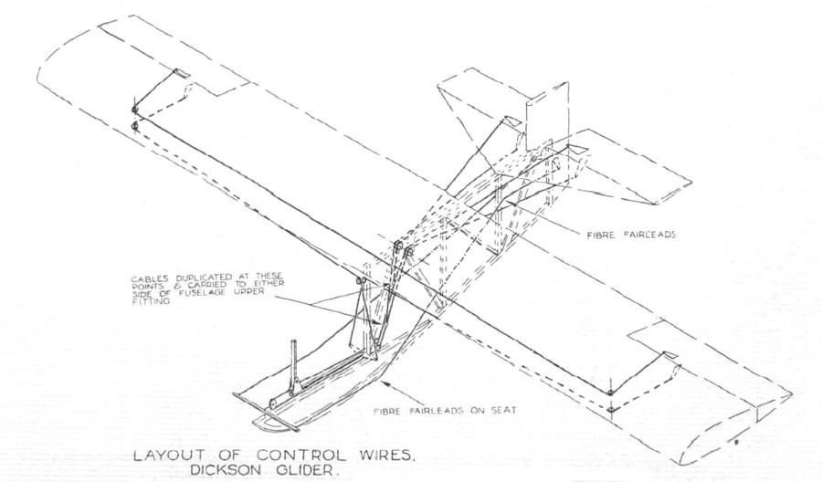
All nuts, pins, turn buckles, etc., must be positively locked by locking wires or washers or similar means. With regard to the wing spars, joints should be made in the plywood web according to the length of the ply available; a piece of ply about 2 in. wide, glued and pinned to the web either side of the joint would be sufficient.
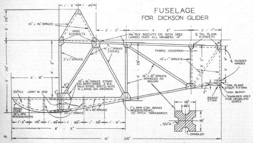
THE DICKSON GLIDER. Last week we published the drawing for the fuselage of this glider and, unfortunately, the designer has informed us that certain dimensions were erroneous. These were :—the front member should have been 2 in. by 1.5 in., and the top longeron and second two truss members should have been 1.5 in. by 1.5 in. The designer regrets that these errors were allowed to pass and hopes that no undue inconvenience has been caused to those building this glider.
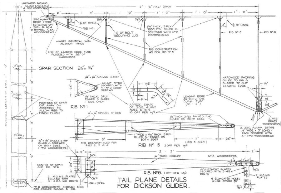
All surfaces should be varnished internally and painted at points where the fabric touches with non-sticking paint. On the main planes the ribs are to be taped together. There should be two lines of tapes running between and parallel to the spars, spaced equally. The tapes are to be run on top and bottom of ribs, crossing through the wing through each pair of ribs, so that from behind or in front the tapes have a lazy-tongs aspect. The fabric should now be sewn to ribs, the stitches being passed right round the whole rib and through the fabric, blanket stitching being used. Each stitch, 2 in. from its fellow, must be knotted.
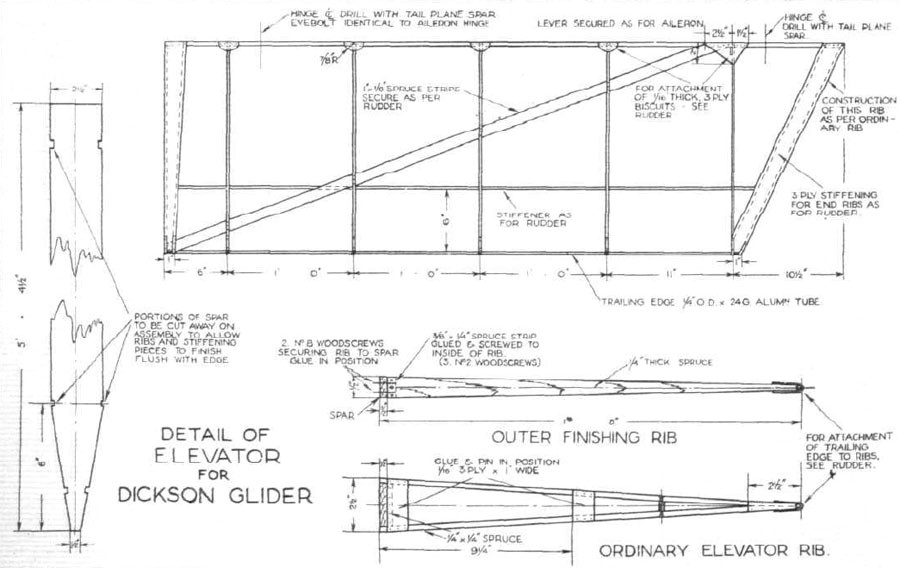
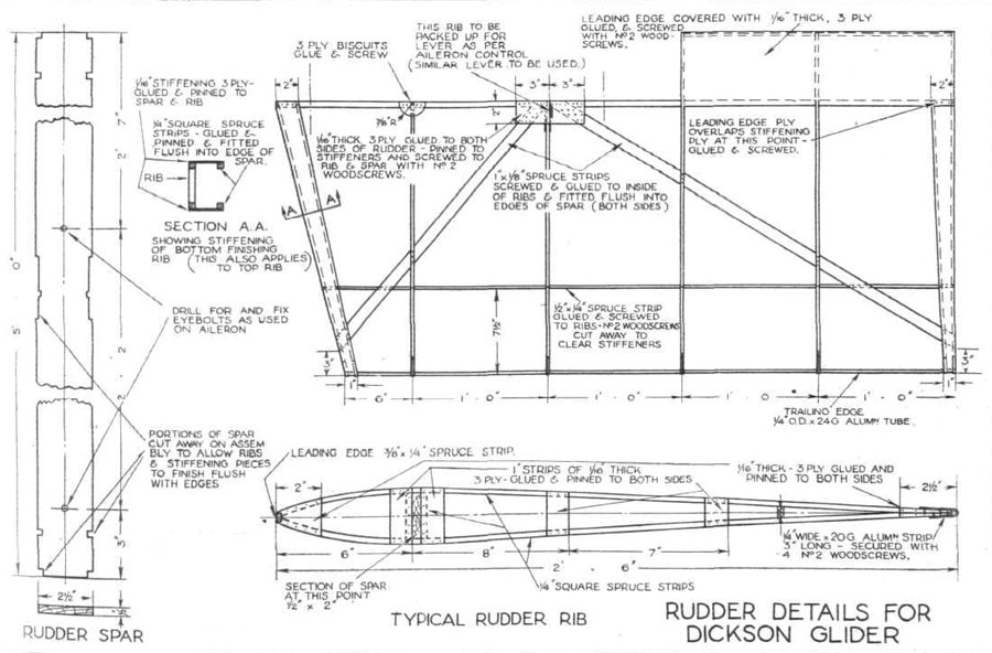
Note that the fabric should not be tacked to the woodwork, but should be sown together to form a sheath. Strips of fabric should be doped on all sewn joints and rib stitching, and the whole surface should now be doped. A scheme of doping can be obtained from any dope manufacturers, who will also supply the right kind of dope for the job. Care must be taken that all components are ” rigged up ” square, and that there is no twist in the wings. The assistance of an aircraft rigger is of great use in this connection. The ailerons should be ” rigged-up ” 2 degrees on both sides. All wooden components must be carefully varnished to prevent damp damaging them. All metal fittings must also be painted. Care must be taken that all wooden parts attached to one another are correctly glued before screwing or pinning.